- Home
- Contact Us
- AAEES Staff
- AAEES Board of Trustees
- American Academy of Environmental Engineers Certification Board
- American Academy of Environmental Scientists Certification Board
- AAEES Committees
- State and Regional Representatives
- Representatives to Other Organizations
- Previous Leadership
- Interactive Who's Who
- Student Chapters
- Tau Chi Alpha
- News & Events
- Awards
- AAEES Awards Criteria
- 40 Under 40 Recognition Program
- Edward J.Cleary Award
- Excellence in Environmental Engineering and Science Education
- Gordon Maskew Fair Award
- Honorary Member
- International Honorary Member
- Ralph and Joe Bales Graber Science Award
- Stanley E. Kappe Award
- Environmental Communications Awards Competition
- Excellence in Environmental Engineering and Science Competition
- The AAEES Chapter Blue Marble Award
- Publications
- Join
- Members
- Program Support
- Jobs
2024 Excellence in Environmental Engineering and Science™ Awards Competition WinnerGrand Prize - Industrial Waste Practice
NW Natural Gas Interceptor Trench Remediation ProjectEntrant: Aponowich, Driscoll & Associates, Inc. with Sevenson Environmental Services, Inc. (Contractor/Operator) Entrant Profile Aponowich Driscoll & Associates Inc (ADA) is an international environmental engineering consulting firm based in Atlanta Georgia and Abreu Dominican Republic, which has operated in over 35 countries. In the United States, the firm is focused on treatment of industrial wastewater and remediation of hazardous waste sites. The firm’s principal, Terence Driscoll, P.E., BCEE is a licensed professional engineer in Oregon and four other states and a licensed wastewater operator. He has over 45 years of engineering and operations experience. He is the principal author of the 2008 McGraw-Hill book, “Industrial Wastewater Management, Treatment and Disposal.” Mr. Driscoll prepares the designs for industrial and hazardous wastewater facilities as an independent engineer for Sevenson Environmental Services, a Niagara Falls, NY-based remediation contractor. He has prepared and executed designs on over 50 projects with Sevenson. On the NW Natural site, Mr. Driscoll prepared all process and mechanical engineering calculations and design for the original 800-gpm NW Natural groundwater treatment facility, as well as for the 325-gpm Interceptor Trench Pretreatment facility which is the basis for this application. These services for the Interceptor Trench included:
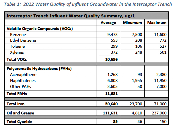
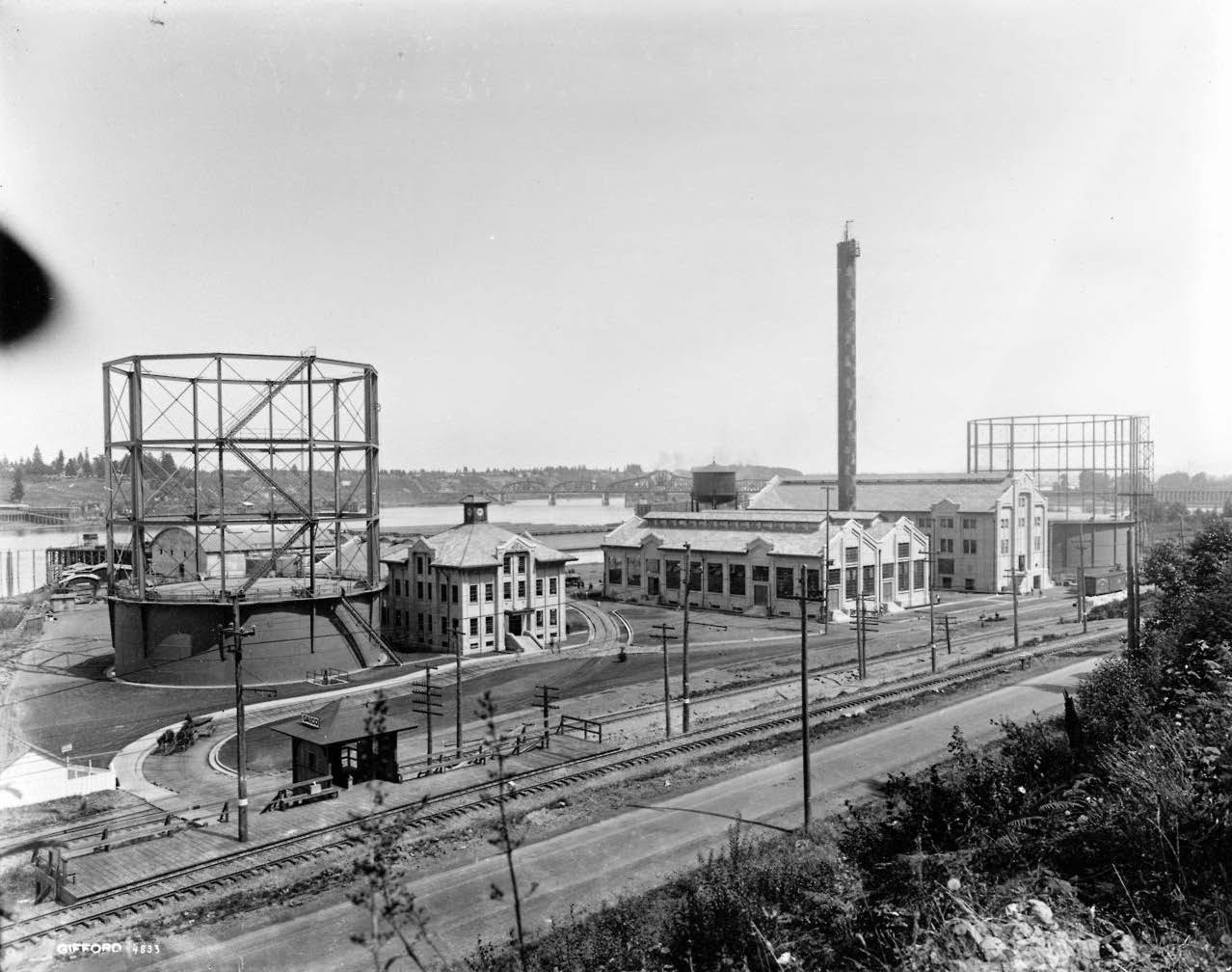
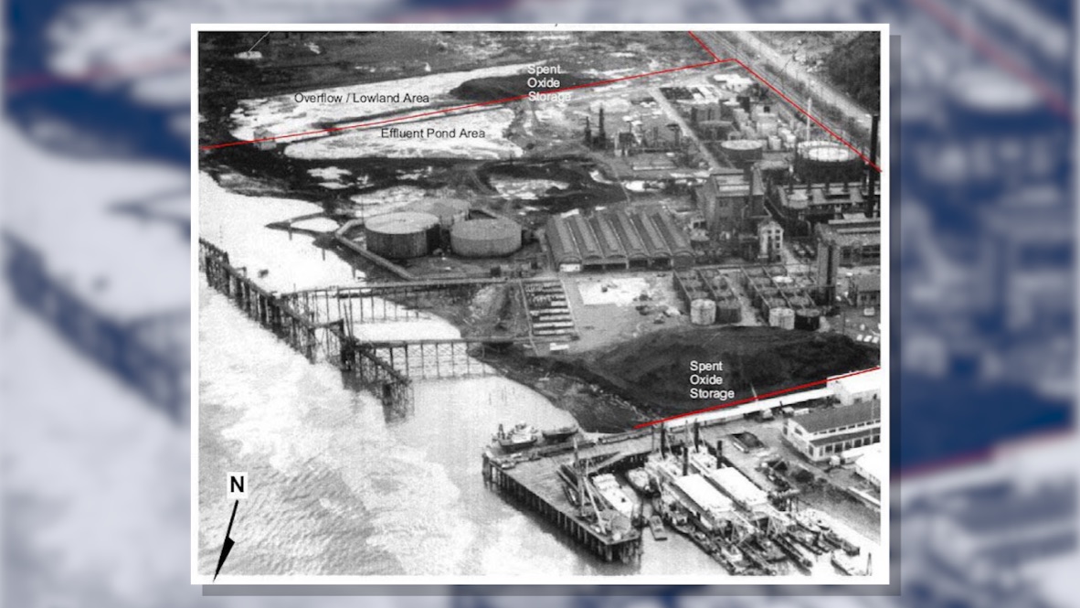
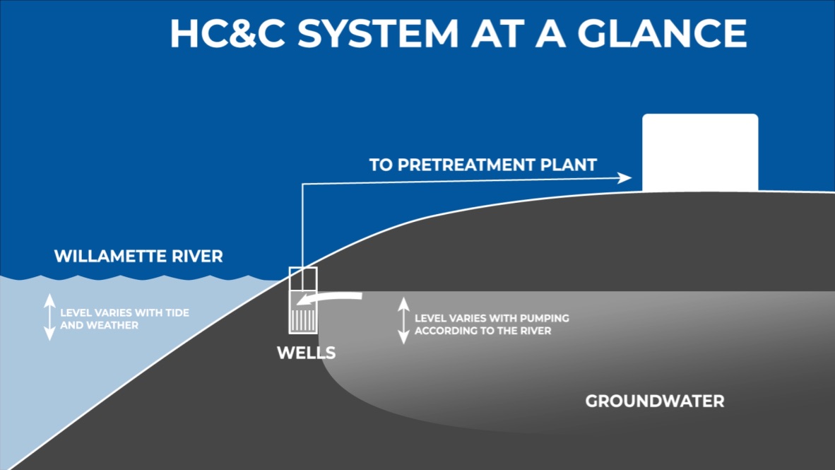
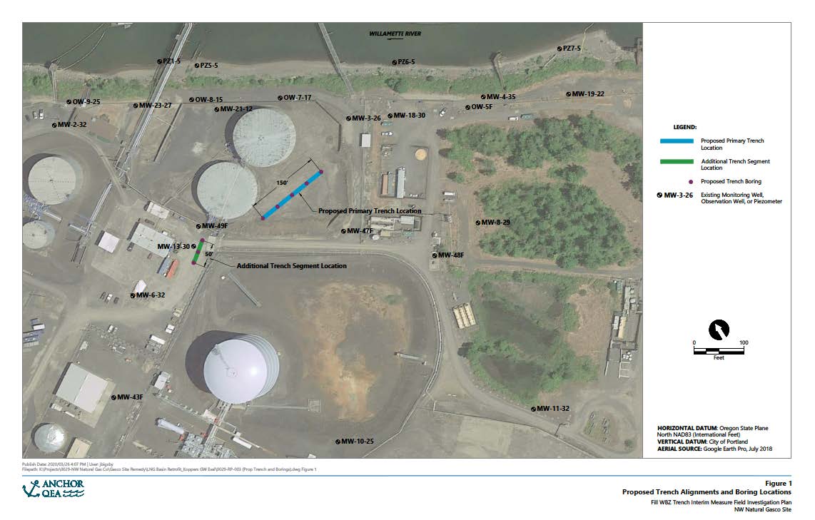
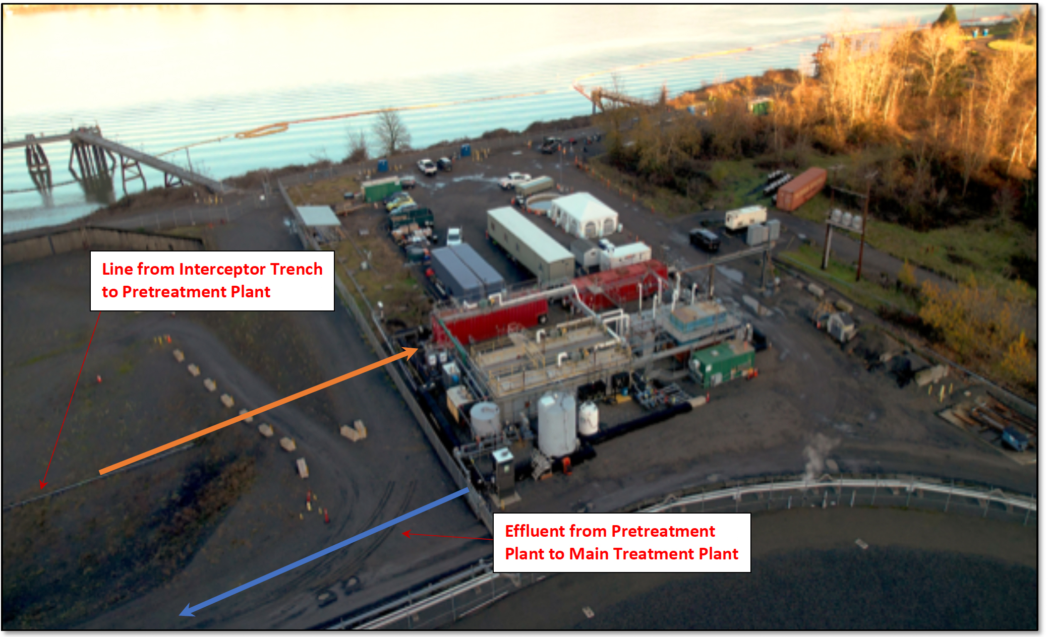
Other design services for the facilities included Glynn Group Engineering and Architects PLLC (Foundations and structural), Anchor QEA (Geotechnical) and Advanced Remediation Technologies (ART) Inc. (Trench well design and instrumentation). Project DescriptionADA and Sevenson Environmental Services (contractor) have been working on the NW Natural Gas site in Portland Oregon since 2008 on an extensive remediation project, removing pollutants from the site being discharged into the Willamette River via groundwater. The 40-acre Gasco Site is on NW Natural's land on the west side of the Willamette River. The project is the first project commissioned as part of the larger Portland Harbor Superfund Site Cleanup. From 1913 to 1956, NW Natural, called the Portland Gas & Coke Company (GASCO) back then, ran a manufactured gas plant on this site as shown in some early photos in Figure 1. As a result of these activities, volatile and semi-volatile organic chemicals, cyanide, and heavy metals were deposited in the soil. High levels of benzene, toluene, xylenes and naphthalenes are present, along with hazardous F002-listed solvents. These wastes were leaching into the Willamette River via the groundwater which crosses the site. A hydraulic control and containment system (HC&C) was designed by others to intercept and capture all contaminated groundwater crossing the site before it reaches the river. Figures 2 and 3 show the workings of the HC&C system. The captured groundwater is pumped by a series of wells across the site to two Pretreatment Plants and to a Main Treatment Plant, which ultimately discharges the treated groundwater back to the river. These facilities began operation in 2013. The Problem and ApproachIn 2020 and 2021, it was determined that the groundwater flow patterns had changed over 8 years of operation. Additional measures were necessary to prevent this groundwater source from reaching the river. This groundwater showed much higher pollutant levels than existing flows. A new pretreatment system was required to collect and treat the so-called “Interceptor Trench” groundwater. The new system would then be tied into the existing Pretreatment Plant and ultimately pumped to the Main Treatment Plant for further treatment and final discharge. The layout of the trenches is shown in Figure 4. Table 1 is a summary of the pollutant levels found in this new source in 2022. The table shows a mixed wastewater with very high levels oil and grease, volatile organics, polyaromatic hydrocarbons, iron, and total cyanide. The oil was found to be mechanically emulsified and therefore didn’t readily settle or float. Also, the iron content was in the ferrous form, meaning it was almost completely soluble. The challenge was how to reduce or eliminate these pollutants prior to discharge to the existing treatment facility, particularly the oil and grease and soluble iron. At the same time, reducing volatile organic compounds and naphthalenes in the Pretreatment Plant was necessary to increase the life of the activated carbon media in the Main Treatment Plant. Compounding the problems with the new treatment system was the regulatory requirement that all existing treatment processes were to continue operating on a 24/7 basis, even during construction.
Complexity of the ProblemThe problems posed by the “soup” found in the Interceptor Trench groundwater included:
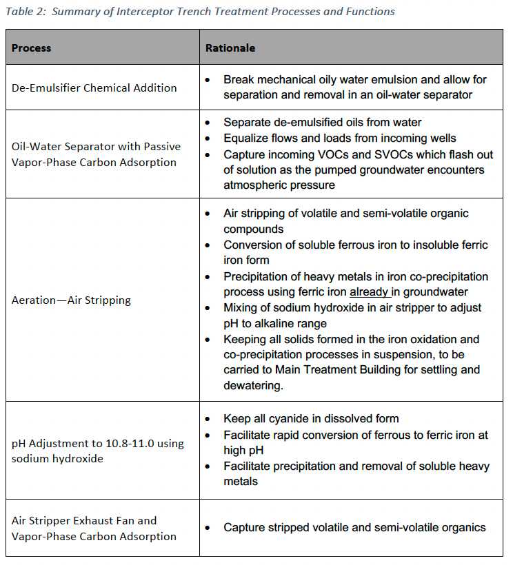
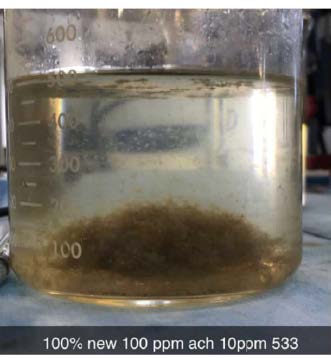
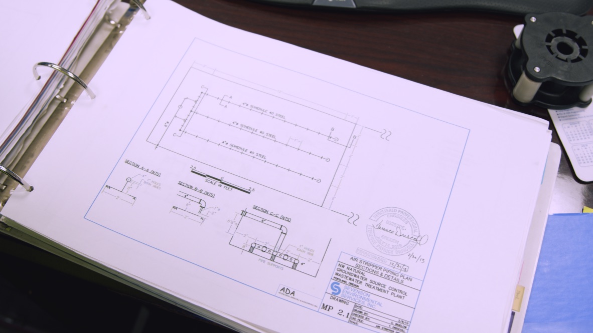
Treatability StudiesAs a first step, ADA directed treatability studies using de-emulsifying chemicals to determine if they could “break” the oily water emulsion. These tests were successful as shown in Figure 5, using a polyaluminum chloride product. DesignThe pretreatment processes developed and designed by ADA for the Interceptor Trench are summarized in Table 2 and described below. A copy of the design data is included at the end of the section.
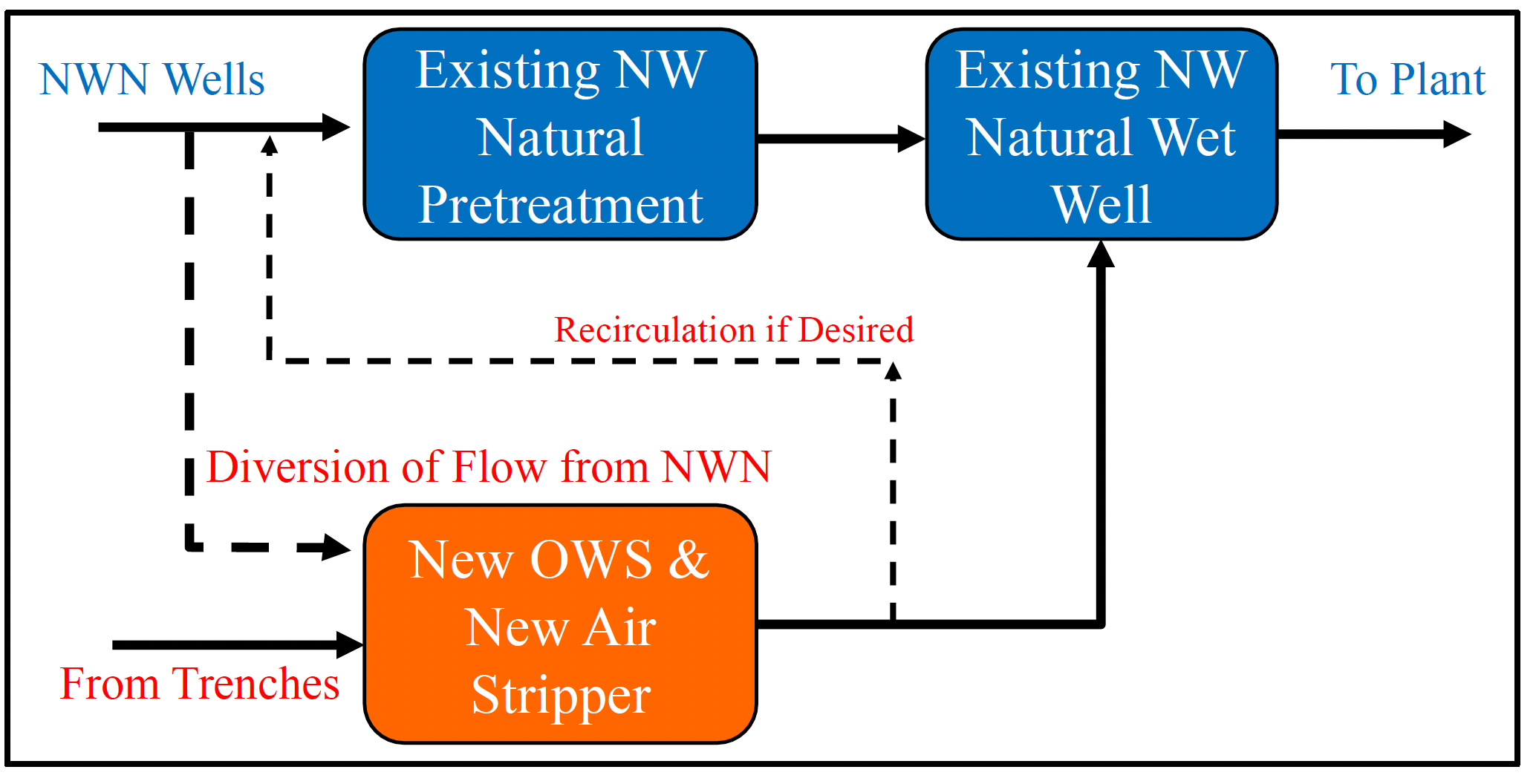
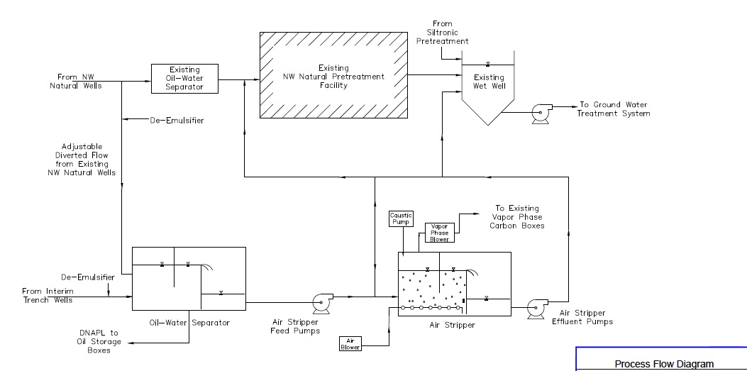
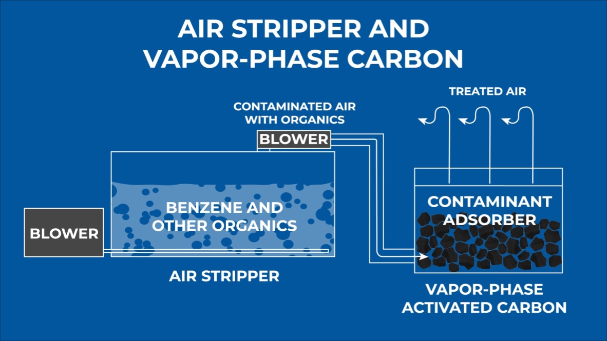
Figure 6 shows a general schematic of the design approach (in orange) adopted by ADA in addressing these issues and the tie-in to the existing NW Natural Pretreatment Plant. The Interceptor Trench Pretreatment Plant is designed for a maximum flow of 325 gals/minute. Figure 7 is the process flow diagram for the plant showing key processes to address the problems discussed in the previous section. Oily Water De-Emulsification and Removal. Referring to Figure 7, a de-emulsifying chemical is first added to the incoming flow to break the mechanical oily emulsion ahead of the oil-water separator (OWS). The OWS is designed to both remove floating and settling oil and provide needed flow equalization capacity for the Pretreatment Plant. Passive Vapor Phase Carbon. The OWS is a covered unit to prevent odors and organic compounds in the incoming flow from escaping to the atmosphere. Because the flow entering the OWS is variable, ranging from zero to a maximum of 325 gpm, the gases in the space above the water surface fluctuate. To capture these gases, all displaced gases pass through a passive vapor carbon system located on top of the closed OWS. Aeration and Air Stripping. A diffused-air stripper was specifically designed by ADA for this purpose, as conventional tower air strippers or tray air strippers would quickly clog, with the iron concentration exceeding 50 mg/L. The iron already in the groundwater is used to precipitate heavy metals (lead and mercury) in the iron co-precipitation reaction. Therefore, no outside coagulants are necessary for metals removal. The air stripping step was designed to perform three functions within the same process:
The schematic of the diffused-air, air stripping process is shown in Figure 8. Vapor-Phase Carbon Adsorption. The Air Stripper designed by ADA is also a closed-top unit, to prevent stripped VOCs and SVOCs from simply crossing from water media to air. A separate exhaust blower collects all exhaust air from inside the air stripper and discharges those gases to a 16,000-pound vessel of vapor-phase activated carbon where they are removed. pH Adjustment. The incoming groundwater is usually slightly acidic: 6.0-6.8. Therefore, sodium hydroxide is added to the Air Stripper in a control loop to raise the pH to 10.8-11.0. As with the other processes, the pH adjustment to this range is intended to achieve a number of process objectives:
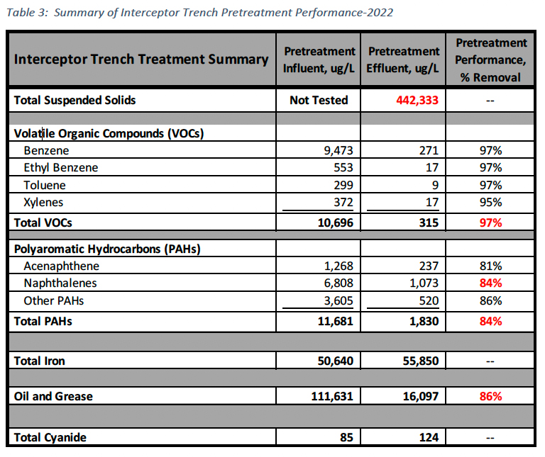
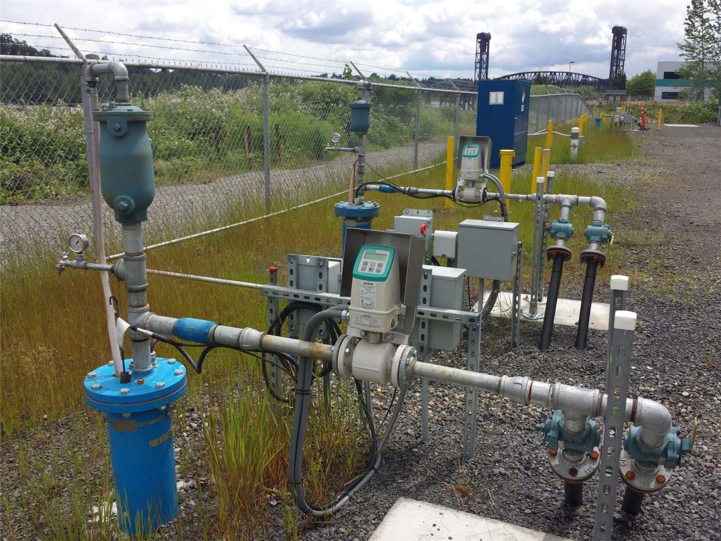
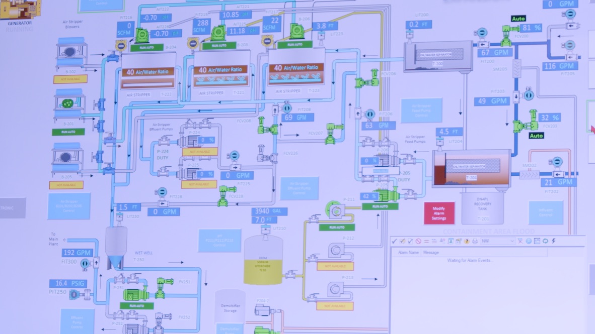
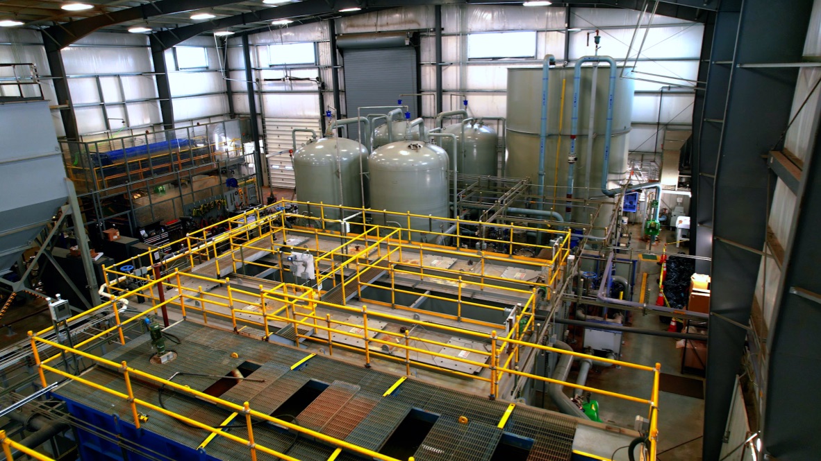
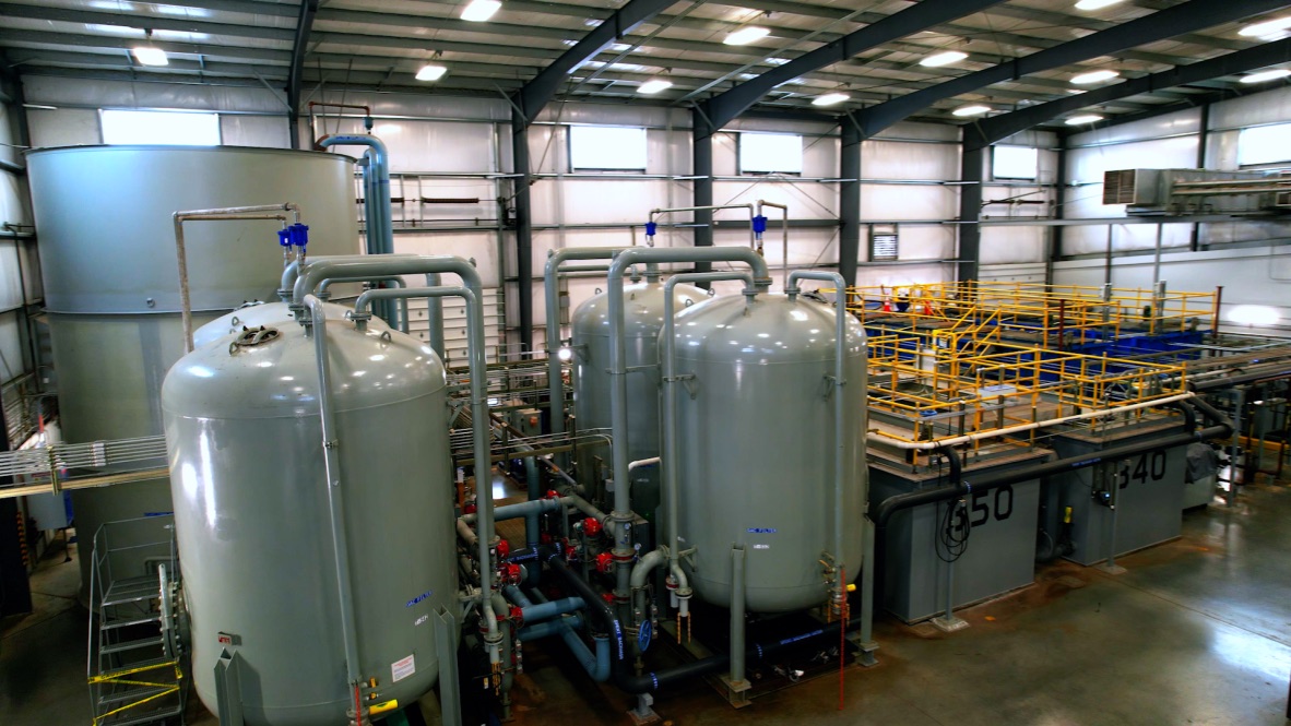
Supervisory Control and Data Acquisition (SCADA) System. The SCADA system for the project was integrated into the existing SCADA system and included flow indication, level indication and control, pH control, and air: water ratio control to the Air Stripper as shown in Figure 9. In addition, process trend capabilities were added to allow the operators to spot and correct problems. The actual constructed Interceptor Trench Pretreatment Plant is shown in Figure 10. Interceptor Trench Pretreatment Plant ResultsTable 3 is a summary of results from the Interceptor Trench Pretreatment processes for 2022. Key takeaways from the data are shown in red. First, influent suspended solids were not tested during the period, as they are typically close to zero. However, the high-pH aeration step creates suspended solids through the oxidation and precipitation of iron and heavy metals as shown in Table 3. These solids are ultimately removed by settling in the Main Treatment Building and dewatered.
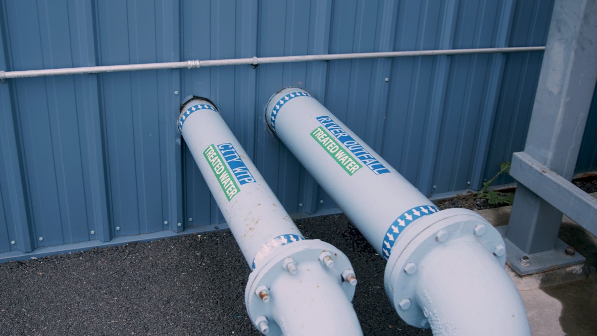
Despite the high levels of suspended solids present in the air stripper, overall VOC removal performance is significant at 97% removal. Original design assumptions were for VOC removal via air stripping was 95-99%, in line with typical design values for air stripping, though outside data for diffused air systems is limited. The level of semi-volatile PAH removal by air stripping, particularly the naphthalenes, was especially notable at 84% removal, much higher than 40- 50% typically predicted. The increased removal efficiency in the Air Stripper resulted in lower organic loading of the liquid-phase activated carbon vessels in the Main Treatment Plant and has doubled their projected life before carbon changeouts are required. Referring to the table, oil and grease removals are significant and have improved further since the 2022 data, with the full implementation of the de-emulsifier chemical program. Precipitated Iron and total cyanide removals were not desired in the Pretreatment Plant, as both are pumped to the Main Treatment Plant for removal by settling and alkaline chlorination, respectively. Project Cost and ScheduleThe final project cost including the trench work and treatment plant was $1.348 million, which was 0.5% less than budgeted. The project took slightly more than a year to complete but was completed on schedule. ImplicationsThere were major concerns in the design process as to whether the high pollutant concentrations and complexity of the incoming waste stream from the Interceptor Trench was treatable at reasonable cost. High dissolved iron and organics concentrations were major concerns, because removing one pollutant (organics) with air exacerbated the other (in the form of increased solids) and potential fouling of a conventional air stripper. Key Takeaways from the project are:
Click images to enlarge in separate window.
Click here to return to the list of 2024 winners. |
||||||||||||||||||||||||||||||||||||

Our Partners