2021 Excellence in Environmental Engineering and Science® Awards Competition Winner
Grand Prize - Design
Logan Township MUA 0.5 MGD Water Reclamation Facility Expansion
Entrant: Remington & Vernick Engineers Engineer in Charge: Richard B. Czekanski, P.E., BCEE, CME Location: Logan Township, New Jersey Media Contact: Richard B. Czekanski, P.E., BCEE, CME
Entrant Profile
Remington & Vernick Engineers (RVE) is one of the oldest established consulting firms in the country and has successfully completed thousands of engineering, planning and capital infrastructure improvement projects for our utility clients. Our staff of specially trained professionals has extensive expertise in developing effective short and long- range plans for water and wastewater systems. We carefully evaluate every system blending proven technology with innovation to ensure all our clients receive systems with maximum efficiency and minimal overall costs.
RVE performed design engineering services and material shop drawing reviews for the Logan Township Municipal Utilities Authority (LTMUA) 0.50 MGD Water Reclamation Facility Expansion Project. When the project design was initiated in 2015, LTMUA knew industrial parks within the Township were being rapidly developed. Within the industrial parks were warehouses and food processing facilities which discharged wastewater with pollutant characteristics of higher concentrations than average wastewater.
In anticipation of this additional flow, RVE designed the improvements that were constructed at the water reclamation facility on a narrow 70’ wide strip of land at the rear of the site. This project included the addition of 500,000 gallons per day of wastewater treatment capacity by the construction of sequencing batch reactor (SBR) tank 3, expansion of the equipment controls building, addition of a 1,500-kilowatt emergency generator and a new electrical service with associated electrical switchgear and transformer. The project design met the needs of the LTMUA’s service area, permitting the ongoing development and economic growth.
DRONE FLYOVER VIDEO: RVE’s inspection drone completed a flyover of the project area and captured video footage in addition to still images. Please note that the video has accompanying voiceover narration, so please ensure sound is on when viewed.
Project Description
Integrated Approach
Waterbodies and freshwater wetlands limit the available area for plant expansion. Only the center of the plant site is beyond the 150 feet wetlands buffer lines which are created based on the wetlands present on all four sides.
Based on the limited developable area, past reports identified that one of the two plant “polishing lagoons,” would be the site of the proposed third sequencing batch reactor (SBR) tank.
The key aspect for the entire project was RVE involving New Jersey Department of Environmental Protection (NJDEP) personnel early in the design/permit application process. Based on consideration of both environmental and operational aspects discussed at a meeting of project stakeholders, the NJDEP favored locating the proposed SBR near the existing two SBRs. The main reason for the tank placement in this location was the existing tanks extend 17 feet above grade; therefore, the NJDEP was concerned an additional taller freestanding above grade tank would pose a danger to any low flying eagles known to habitat the area.
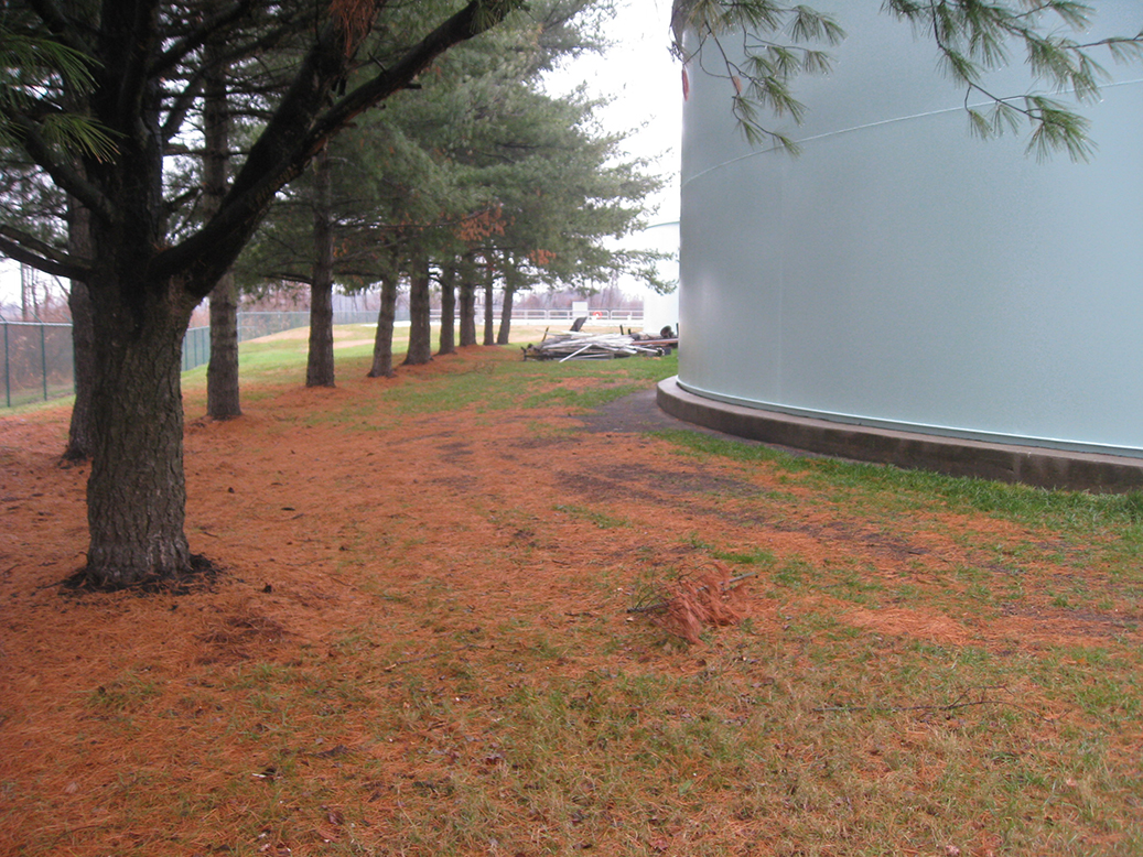
In an area beyond the two existing SBRs there is a 60’ – 79’ wide rectangular strip of land bounded on one long sides by the two SBRs and the freshwater wetlands line/wooded area on the other. Once constructed, the proposed SBR was in close proximity to these limitations by being only six feet from one existing SBR; 12 feet from one polishing lagoon and five feet from the wooded area associated with the wetlands line. During construction, both existing SBRs and the polishing lagoon system remained in service. In this strip there were existing spruce trees which were removed, so willow oak trees were provided as mitigation in another location on-site.
See drone flyover video uploaded in the secured drop box for integrated site layout.
Quality
Through the construction of a retaining wall parallel to the wetlands line and regrading on the plant side of the wall, the LTMUA gained useable land that houses the electrical switchgear/transformer facility; the emergency generator facility and SBR Tank #3. Overall, this maximizes the use of an environmentally sensitive site.
The existing floor elevation of the equipment/controls building was at the 100-year flood elevation so all building improvements (pumps; blowers; electrical panels) and ancillary equipment (electrical switchgear/transformer and emergency generator facility) were located at least one foot above floor level and thereby out of the 100-year flood elevation.
With three operational SBRs the ability to feed at least one SBR at any one time reduces the detention in the plant’s equalization tank. This is meaningful during wet weather events.
Previously the two existing SBRs were provided compressed air by two blowers. Now there are four blowers supporting the operations in three tanks. With the spare blower, the operational capability of the process treatment was upgraded.
With two laptops provided with the new SBR control system, operators possess remote capability to monitor and control the SBR facilities.
Most importantly, overall SBR treatability has increased due to the design of a higher pollutant strength loading capability for the proposed SBR.
Originality and Innovation
SBR tanks are typically round. To maximize the site land use, the SBR was designed as a rectangular tank.
SBRs are unique as in one tank the wastewater proceeds through aeration, mixing and settle cycles resulting in overall less land space than conventional wastewater treatment plant processes.
SBR piping systems have valving incorporated, enabling the same pump to mix the tanks contents during lull periods and when the need to waste settled sludge exists, the valves are re-set to maintain the appropriate settled sludge level in the tank. This valve resetting and change in operations is easily accomplished.
To minimize disruption due to vibration along with structural support of SBR Tank 3, 286 14-inch diameter cast-in-place ground improvement elements (CGE) were included in the design. The CGEs are more advantageous than wood piles since there is less chance of settlement of the surrounding area due to the lack of significant vibration.
Complexity
The plant is an active wastewater treatment facility and specification direction was provided to the contractor for 12 different temporary, coordinated shutdowns where the LTMUA had to perform manual equipment operation.
The two existing SBRs were associated with a 40-foot wide by 20.5-foot long by 10-foot clear interior height equipment/controls building with a flat roof. This crowded equipment/control building contained one individual set of piping, valving, air supply blower and SBR react pump for each of the two SBR tanks. As shown on the preconstruction photos, the pumps and blowers were in the building interior, but all the air and wastewater piping associated with the SBR tankage was outside of the building.
To accommodate the proposed third SBR tank and provide one coordinated, accessible equipment/controls area, the building was expanded to 40 feet wide by 53.5 feet long by 20 feet clear interior height with an A- frame roof constructed above the ceiling. The existing air and wastewater piping that was previously on the building exterior was now positioned in the interior at approximately the building midpoint.
Social or Economic Advancement
The project meets the needs of the LTMUA and the public the LTMUA serves and supports the ability of the water reclamation plant processes to successfully treat the influent wastewater. It contributes to the overall public health of the served municipalities while meeting the treatment capability demand from large industrial parks containing food producing manufacturers. From an energy standpoint, all the motors used were high efficiency and all lighting, from utilization for control panel indication to site lighting, used LED long lasting lights.
The project is an example of cooperation between the NJDEP and the LTMUA by allowing a limited space of wetlands transition area to be used for treatment processes without losing any of the polishing lagoons. Nature was preserved; the woods line associated with the adjacent wetlands line was not affected by the construction. The new facilities were fit into a small strip of land bordered by wetlands to protect low flying eagles from colliding with freestanding tankage.
Click images to enlarge in separate window.
PRE-CONSTRUCTION PHOTOGRAPH: The rear of the equipment/controls building with original air and wastewater piping associated with the SBR tankage on the exterior. At a later phase in construction, the building height was doubled.
PRE-CONSTRUCTION PHOTOGRAPH: View from the southeastern site corner with existing SBR Tank 1 on the right. The narrow area between the tank and fencing on the left is the proposed location of SBR Tank 3. Numerous subsequent photos were taken from the same viewing location.
C
PRE-CONSTRUCTION PHOTOGRAPH: The original SBR blowers serving SBR Tanks 1 and 2. The rear building wall shown was demolished at a later phase of construction.
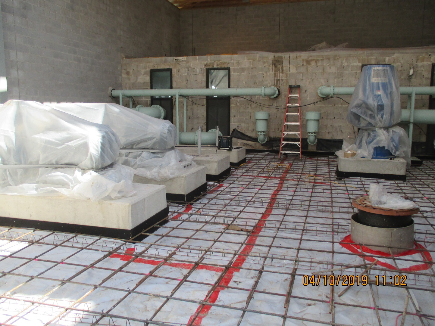
ONSTRUCTION PHOTOGRAPH: Existing equipment/controls building with roof removed and expanded building foundation footing constructed. The four parallel concrete pads support one blower each while the one square concrete pad supports the proposed SBR Tank 3 react pump.
CONSTRUCTION PHOTOGRAPH: Construction of the equipment/controls building interior. The existing wall and piping were still in place, as existing plant operations were required to be maintained in operation. Blowers are on the left and the SBR react pump is on the right.
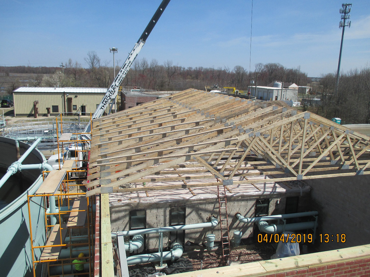
CONSTRUCTION PHOTOGRAPH: Construction of the equipment/controls building A-Frame roof on top of the extended height walls. The existing wall and piping were still in place to maintain existing plant operations. At a later phase in construction, the wall was demolished and the piping was modified.
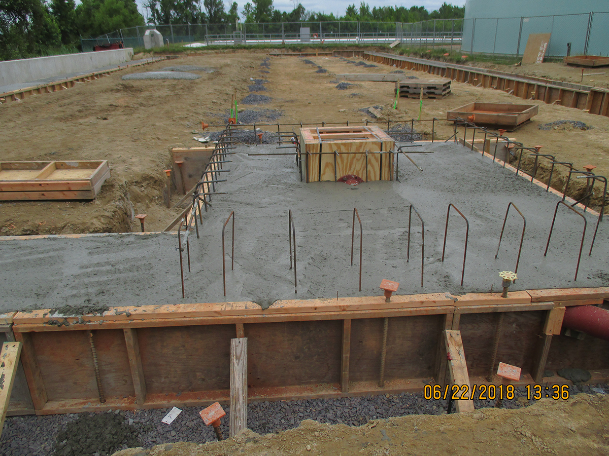
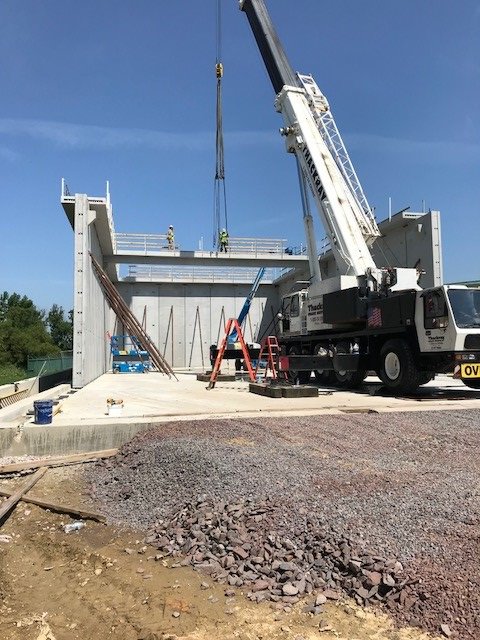
CONSTRUCTION PHOTOGRAPH: Proposed SBR base slab construction in close proximity to new retaining wall on left and existing SBR tank on right. Some CGE elements are visible at each stone pile.
CONSTRUCTION PHOTOGRAPH: Proposed SBR at mid construction during setting of precast walkways.
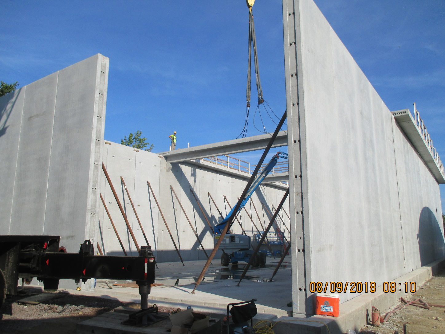
CONSTRUCTION PHOTOGRAPH: SBR Tank 3 wall construction nearing completion. The walls were manufactured off-site, trucked to the site and field erected. One method to secure the walls in place was the insertion of post tensioned cables through the openings shown.
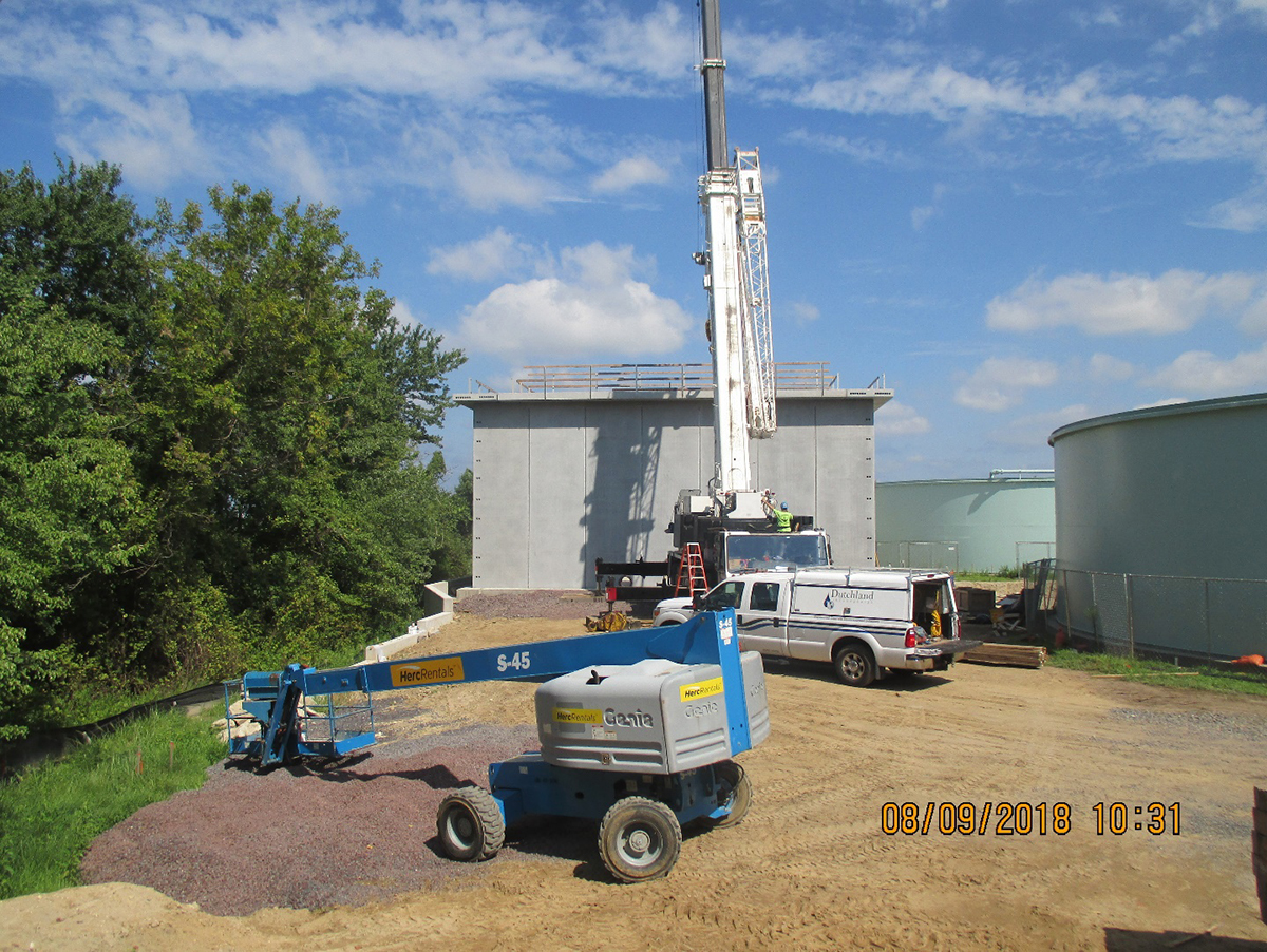
CONSTRUCTION PHOTOGRAPH: View from the southeastern site corner with existing SBR Tank 1 on the right. The retaining wall on the left separates the site from an environmentally sensitive area. The center of the photograph is the location of the electrical transformer/switchgear and diesel generator facilities. SBR Tank 3 is in the background.
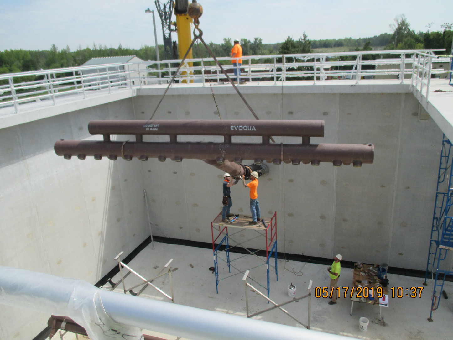
CONSTRUCTION PHOTOGRAPH: Installation of SBR Tank 3 effluent decanter piping. Once a motorized valve on the tank exterior opens, the decanter, which will be floating on the water surface, will convey the treated wastewater to the tank discharge piping.
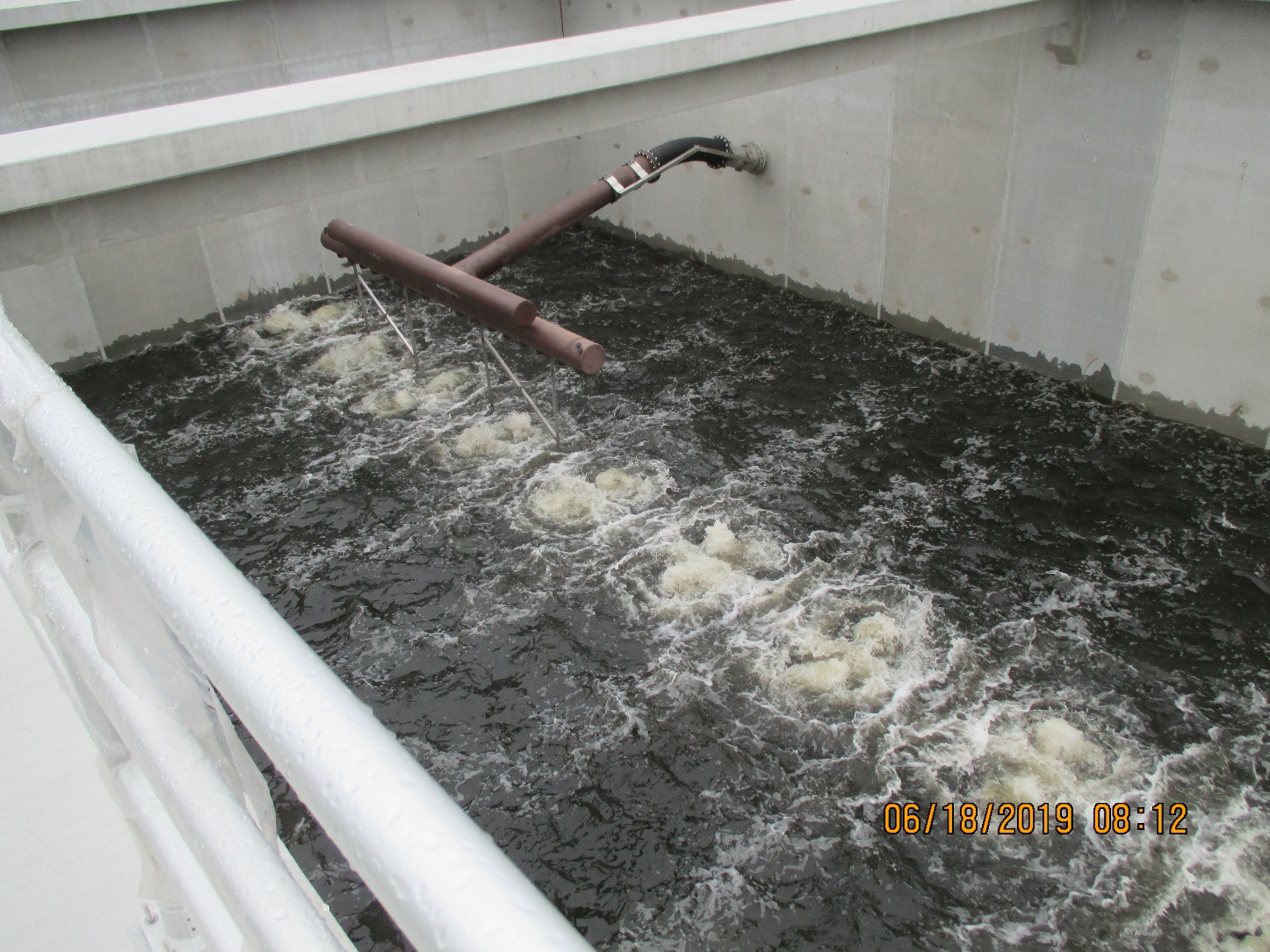
CONSTRUCTION PHOTOGRAPH: Preliminary SBR Tank 3 aeration system operational testing with water at the lower tank fill level. Effluent decanter shown in the background. Once sufficient wastewater is added, the decanter wall elbow will flex, allowing the decanter to float on the water surface.
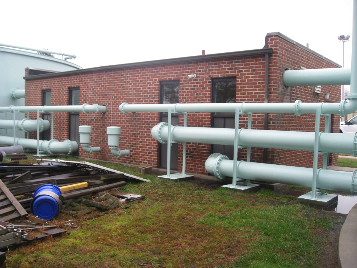
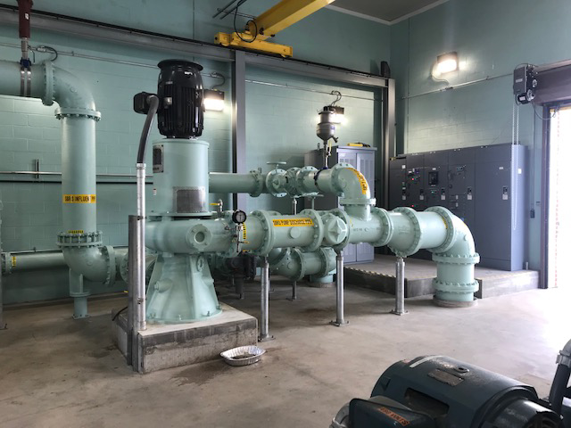
POST-CONSTRUCTION PHOTOGRAPH: A close-up view of the expanded equipment/controls building, emergency generator and newly constructed SBR Tank 3 (rectangular tank).
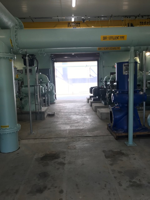
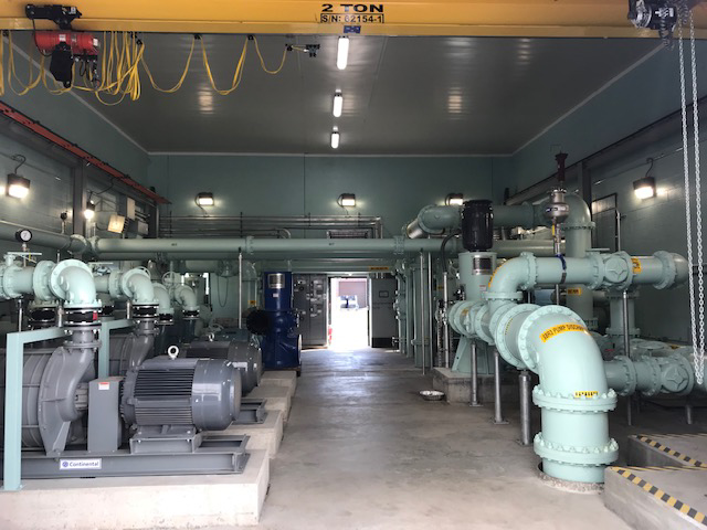
POST-CONSTRUCTION PHOTOGRAPH: View in the equipment/controls building looking beyond towards SBR Tank 3. The two rectangular outlines on the floor are the previous location of the two blowers shown in the pre-construction photos.
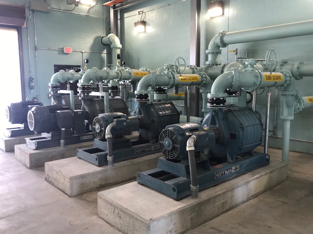
POST-CONSTRUCTION PHOTOGRAPH: Newly installed SBR blowers. Two relocated blowers from an earlier photo on the right and two pre-purchased blowers on the left.
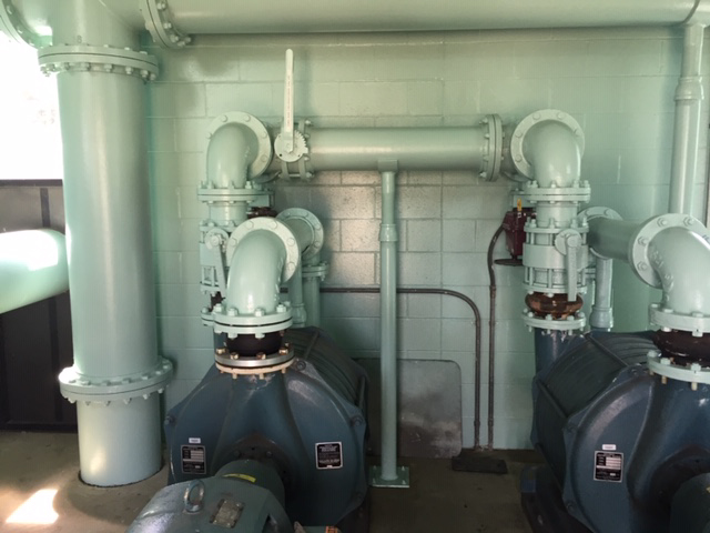
POST-CONSTRUCTION PHOTOGRAPH: New SBR Tank 3 react pump, valving and piping. Valving permits the pump to provide new wastewater flow to the tank or recirculate the flow enabling its mixture with air from the blowers for tank aeration. Electrical motor control and automatic transfer switch panels are in the background.
POST-CONSTRUCTION PHOTOGRAPH: View in expanded equipment/controls building looking from SBR Tank 3. The existing building walls have been extended, the rear wall was demolished and the air piping was modified.
POST-CONSTRUCTION PHOTOGRAPH: View from the southeastern site corner, with existing SBR Tank 1 on the right, expanded equipment/controls building and existing SBR Tank 2 on the far right, new SBR Tank 3 with access stairway in the middle and platform accessed diesel generator on the left. View is from a similar location as the second photo with SBR tank 1 on the right.
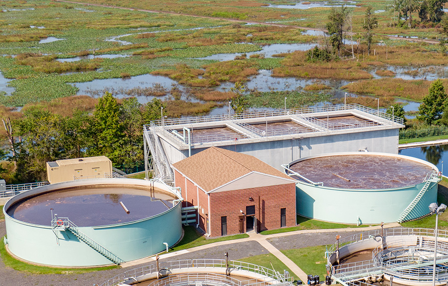
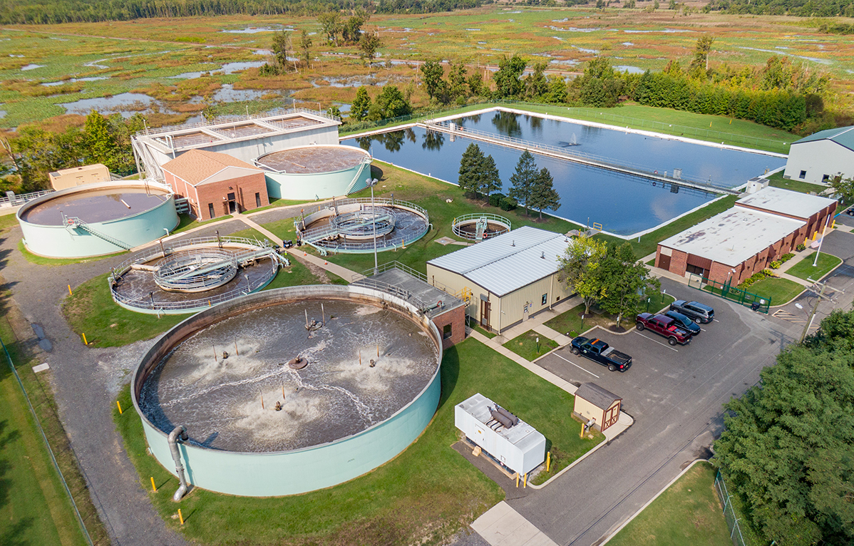
POST-CONSTRUCTION PHOTOGRAPH: An aerial view of the overall site captured by RVE’s inspection drone, with the environmentally sensitive areas surrounding the plant site.