- Home
- Contact Us
- News & Events
- Awards
- AAEES Awards Criteria
- 40 Under 40 Recognition Program
- Edward J.Cleary Award
- Excellence in Environmental Engineering and Science Education
- Gordon Maskew Fair Award
- Honorary Member
- International Honorary Member
- Ralph and Joe Bales Graber Science Award
- Stanley E. Kappe Award
- Environmental Communications Awards Competition
- Excellence in Environmental Engineering and Science Competition
- The AAEES Chapter Blue Marble Award
- Resources
- AAEES Microcredentials
- Annual Reports
- AAEES Press Releases
- AAEES Website How To VIdeos
- Environmental Engineer and Scientist
- Environmental Engineering Body of Knowledge
- PFAS Resources
- Specialty Examination Guide
- Students and Young Professionals Resources
- Who's Who in Environmental Engineering & Science®
- Leadership Opportunities
- Membership
- Donate
- Jobs
2022 Excellence in Environmental Engineering and Science® Awards Competition Winner
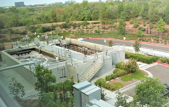
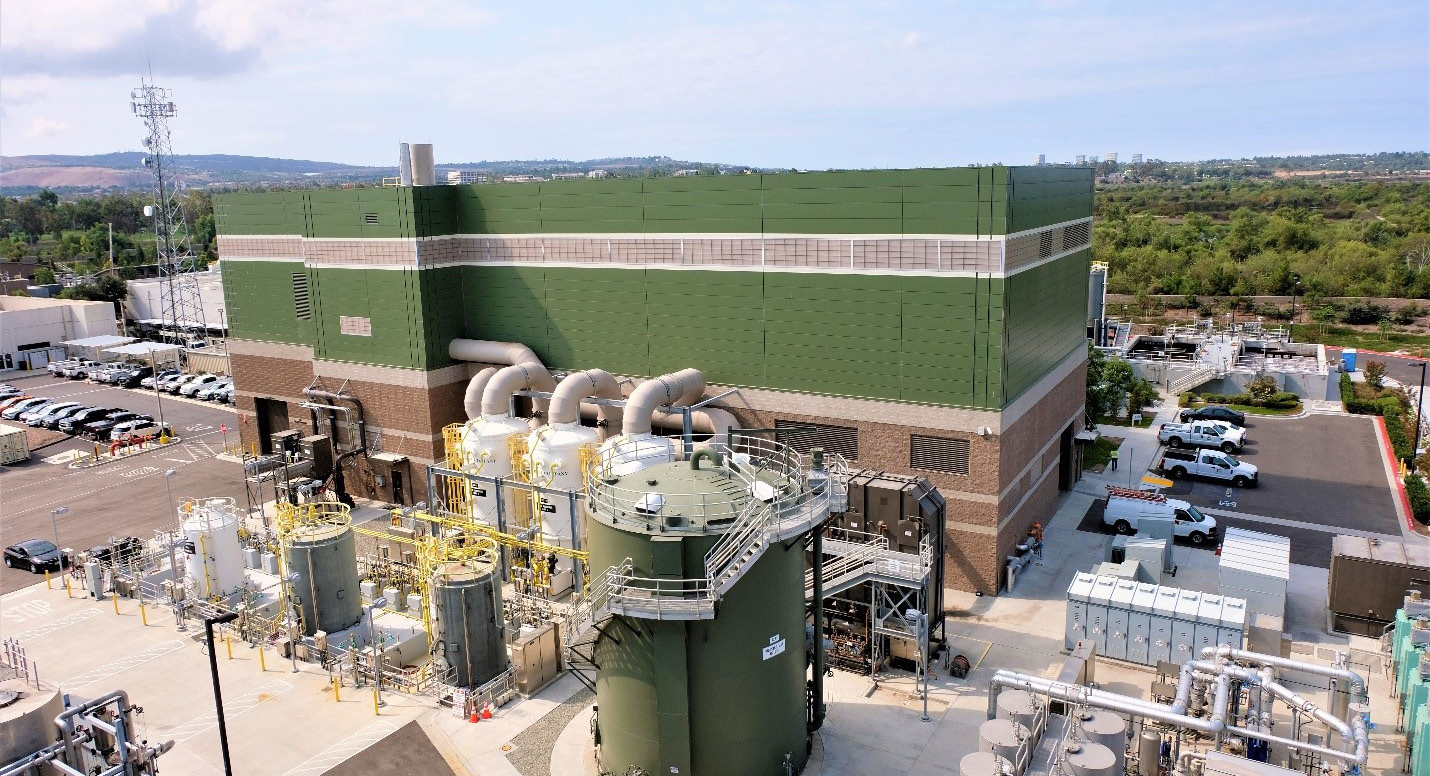
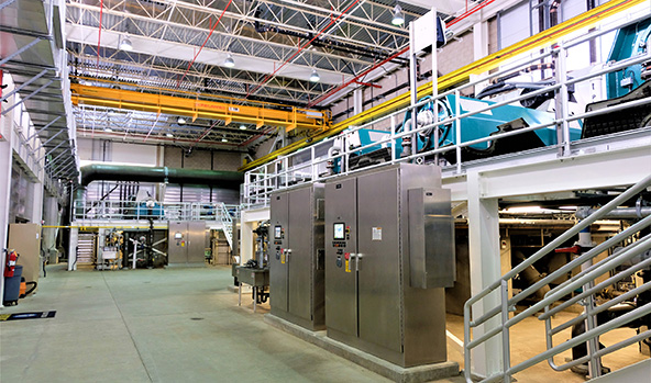
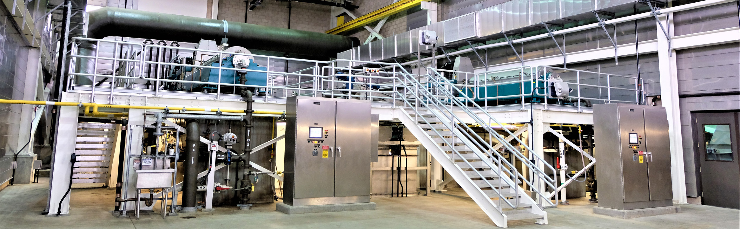
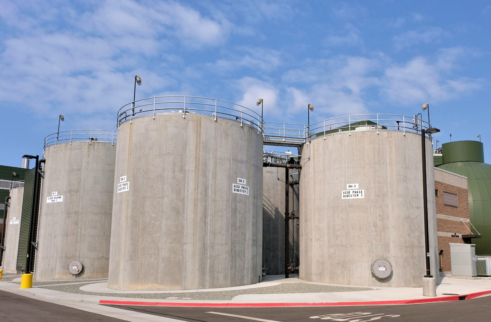
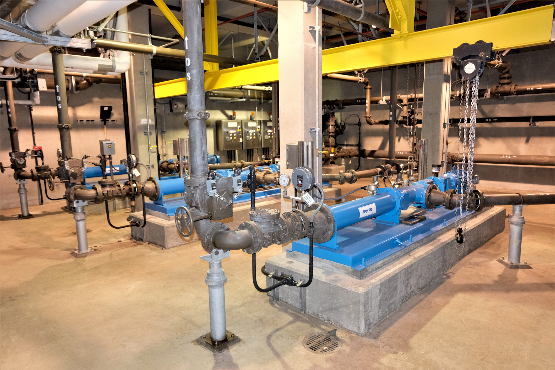
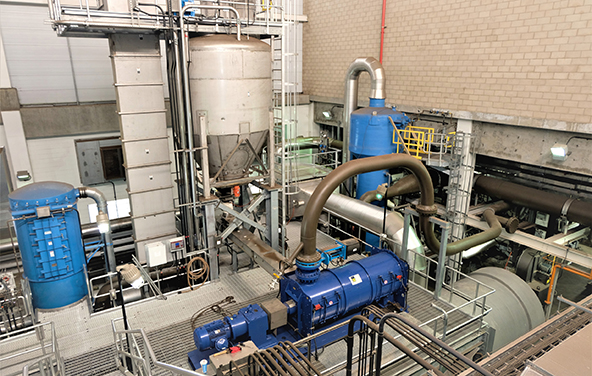
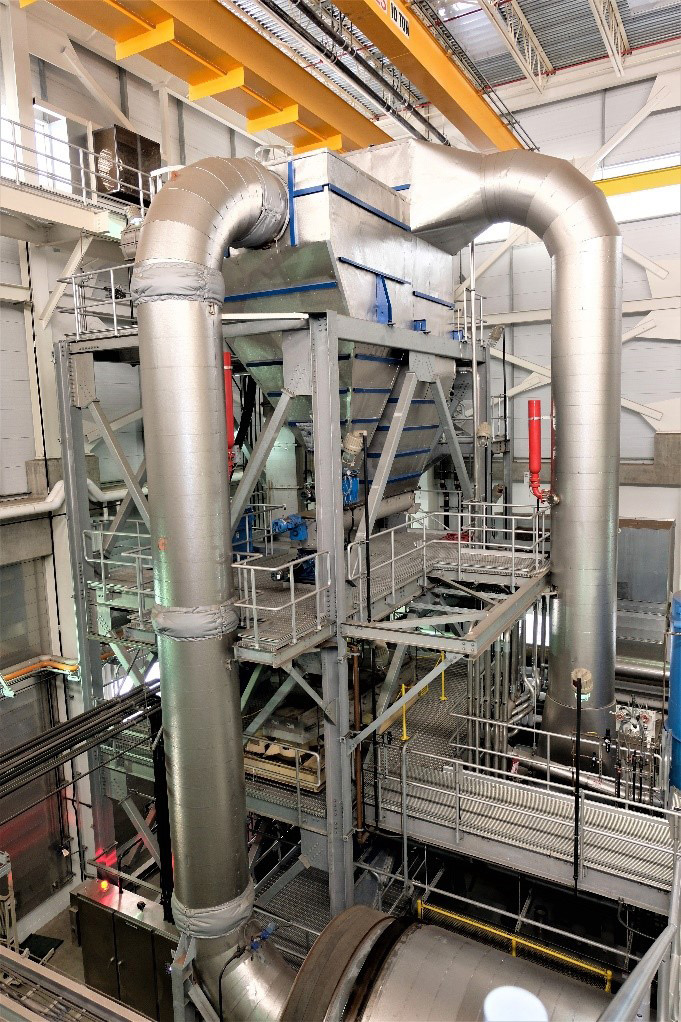
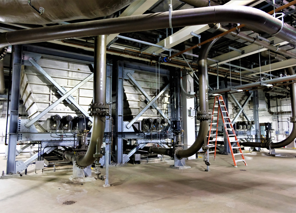
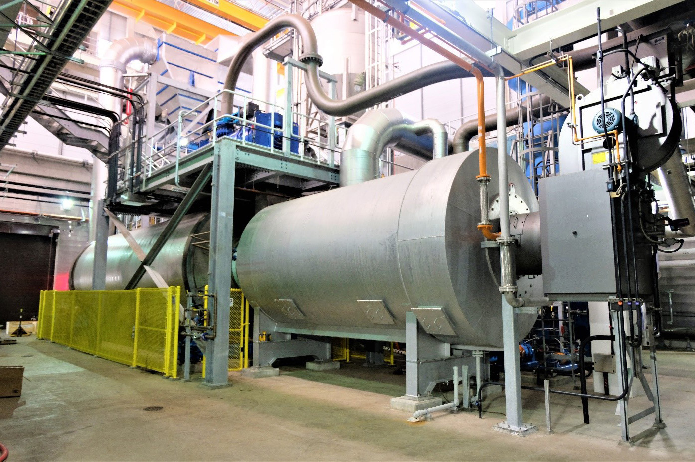
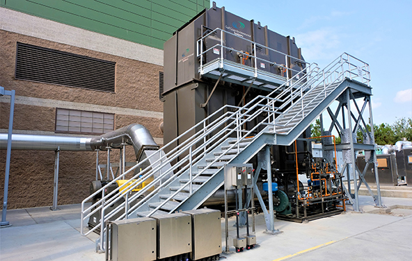
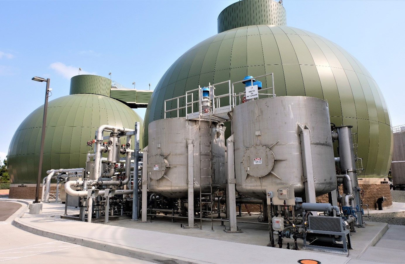
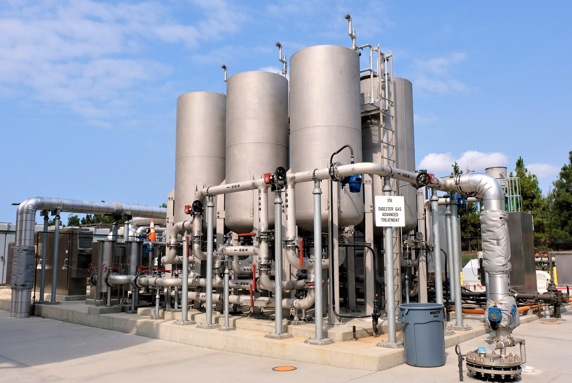
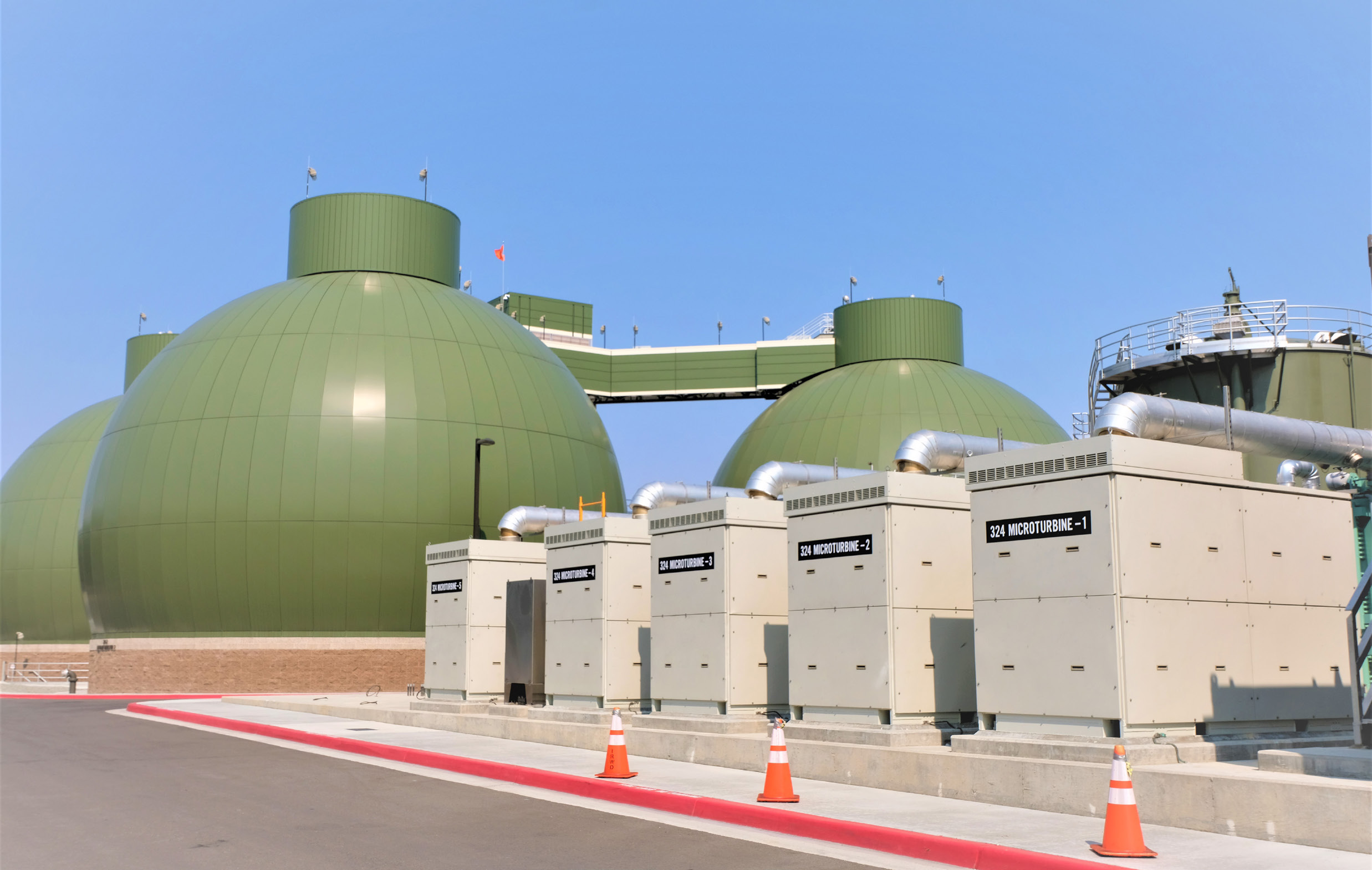
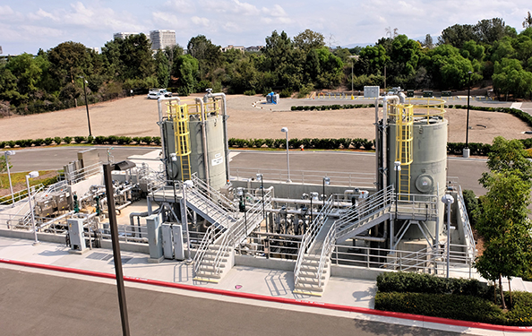
Honor Award - DesignMichelson Water Recycling Plant Biosolids and Energy Recovery FacilitiesEntrant: Black & Veatch Entrant Profile Black & Veatch (BV) provides integrated engineering, procurement, consulting, and construction services to public and private clients, promoting the resilience and reliability of infrastructure assets that improve the quality of life. The company has nearly 100 years of experience in biosolids processing and management. It designed the Biosolids and Energy Recovery Facility to process all biosolids produced at the Irvine Ranch Water District’s Michelson Water Recycling Plant, use the energy and heat generated during solids processing, and deliver a final product for beneficial use as fertilizer or e-fuel. Project DescriptionOverviewThe Irvine Ranch Water District (IRWD) added complete biosolids handling and treatment facilities to the Michelson Water Recycling Plant (MWRP) following a project to expand the plant’s capacity to 28 million gallons per day (MGD). Previously, all biosolids from the MWRP were conveyed to a neighboring agency for processing, reuse, and disposal. IRWD decided to implement solids handling facilities at the MWRP based on economic and non-economic factors in support of its mission to “provide reliable, high-quality water and sewer service in an efficient, cost-effective manner and environmentally sensitive way that provides a high level of customer satisfaction.” Integrated ApproachThe new facilities were designed to process all biosolids produced at the MWRP, capture and reuse the energy generated during processing, and deliver a final product that can be used as a commercial fertilizer or fuel. Comprehensive TechnologySludge ThickeningPrimary sludge (PS) and waste activated sludge (WAS) are transferred from the existing liquids process to the new Dewatering Facility for thickening prior to digestion. The facility includes four (4) solid-bowl centrifuges for thickening PS and WAS separately or as combined PS/WAS. Prior to thickening, the sludge is passed through strain presses to remove small inorganic material that could cause plugging in the sludge dryer. Anaerobic DigestionSolids from the thickening process are sent to a two-stage anaerobic digestion process. Step one is the acid phase, done in three concrete acid-phase digesters with an approximate retention time of 1.5 days. Sludge from the acid-phase digesters is pumped to the methane phase (three 1.5 million gallon egg-shaped) digesters. The two-step process provides greater stability in mesophilic anaerobic digestion by prehydrolyzing and pre-acidifying feed sludge, making it more amenable for anaerobic digestion. DewateringAfter digestion, sludge is sent via gravity to two holding tanks that provide intermediate storage prior to the dewatering/drying processes. Dewatering is done through three solid bowl centrifuges, yielding a sludge cake of 22-25 percent dryness for feeding into the dryer. DryingDewatered sludge is fed through a rotary drum thermal dryer, yielding a product with 92 percent dryness. The system includes feed pumps, and the dryer process and emission controls consist of a venturi wet scrubber followed by a regenerative thermal oxidizer. Dried product is stored in two elevated silos with gravity-feed truck loading. Energy RecoveryEnergy recovery in the form of electric power generation and heat recovery was integrated in the design. Gas TreatmentDigester gas goes through a two-step cleaning process to remove hydrogen sulfide and siloxanes prior to use in the dryer, boiler, or microturbines. MicroturbinesEnergy recovery is achieved through five 200-kw microturbines. Treated digester gas is directed to the microturbines for energy production as well as heat production for digester heating. A BTU content monitor is used to monitor BTU content of the gas, with a natural gas blending station to maintain optimum BTU feed to the microturbines. FOG ReceivingThe facility includes a Fats, Oils, and Grease (FOG) receiving station. Trucked-in FOG is screened, heated, and metered into the digestion process slowly to enhance digester gas production, allowing for greater energy recovery. Centrate TreatmentCentrate from the digested sludge dewatering is high in ammonia. To limit impacts on the liquid treatment process, an ammonia-removal process was included. The process consists of two sequencing batch reactors (SBR) that use fine-bubble aeration to biologically remove ammonia from the centrate and allow for settling of solids carryover, which are subsequently collected and returned to the sludge thickening process for treatment. QualityThe final biosolids product meets the Class A requirements for Part 503 of the U.S. Environmental Protection Agency (EPA) Title 40 of the Code of Federal Regulations (CFR). Originality/InnovationThe design provided a fully integrated biosolids treatment system using state-of-the art equipment for thickening, digestion, dewatering, and thermal drying of biosolids while incorporating energy production and waste-heat capture to offset energy consumption. Inclusion of a two-step acid/mesophilic digestion process for increased efficiency further enhances the effectiveness of the biosolids treatment processes. ComplexityChallengesThe new solids treatment facilities were designed to fit in a 6.3-acre corner of the existing treatment plant, requiring careful coordination of the processes to maximize space utilization. Meanwhile, this area of the plant provided additional challenges, as follows. Soil ConditionsSoil conditions, weight of the structures, and project seismic requirements required that all facilities be supported on piles. The use of concrete-driven piles was chosen and, ultimately, more than 3,000 piles were driven to support the biosolids structures. Laydown AreaThe site for the solids facilities is compact. This required, as the facilities were being constructed, careful coordination for crane, equipment, and materials staging. Remote staging areas were also used. Impacts to OperationsDuring start-up of the facility, the impacts of the return flows to the existing liquids processing facilities required coordination from the operations group to get the new facilities integrated into the overall operation of the treatment plant. Contribution to Social, Public, Environment, Economic AdvancementIn addition to the main treatment of the solids, the project added ancillary processes to meet IRWD’s goals of providing a facility that is environmentally responsible and uses the available energy from the treatment process.
Click images to enlarge in separate window.
Click here to return to the list of 2022 winners. |


Our Partners