- Home
- Contact Us
- News & Events
- Awards
- AAEES Awards Criteria
- 40 Under 40 Recognition Program
- Edward J.Cleary Award
- Excellence in Environmental Engineering and Science Education
- Gordon Maskew Fair Award
- Honorary Member
- International Honorary Member
- Ralph and Joe Bales Graber Science Award
- Stanley E. Kappe Award
- Environmental Communications Awards Competition
- Excellence in Environmental Engineering and Science Competition
- The AAEES Chapter Blue Marble Award
- Resources
- AAEES Microcredentials
- Annual Reports
- AAEES Press Releases
- AAEES Website How To VIdeos
- Environmental Engineer and Scientist
- Environmental Engineering Body of Knowledge
- PFAS Resources
- Specialty Examination Guide
- Students and Young Professionals Resources
- Who's Who in Environmental Engineering & Science®
- Leadership Opportunities
- Membership
- Donate
- Jobs
2023 Excellence in Environmental Engineering and Science® Awards Competition WinnerGrand Prize - Design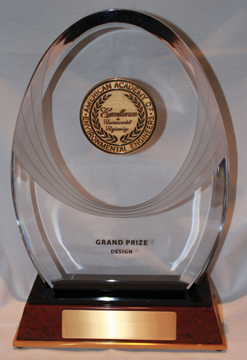
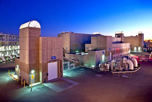
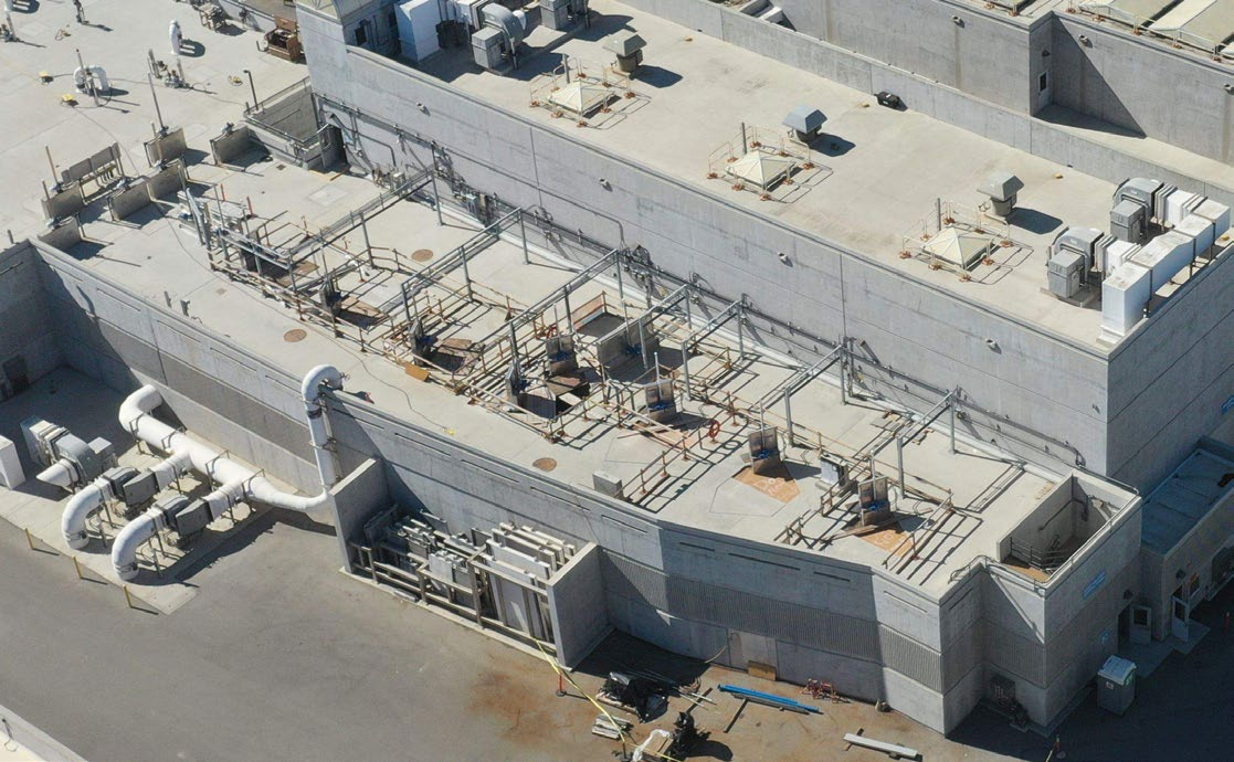
A Headworks Divided - The Key to Unlocking Expanded Water Reuse in Orange County, CAEntrant: Orange County Sanitation District in Partnership with the Orange County Water District Entrant Profile  The Orange County Sanitation District (OC San) is a special district governed by a 25-member Board of Directors comprised of 20 cities, four special districts, and one representative from the Orange County Board of Supervisors. OC San provides wastewater collection, treatment, and recycling for approximately 2.6 million people living within a 480-square-mile area of central and northwestern Orange County, California (CA). Our facilities include 388 miles of sewer pipes, located throughout the county. Together both plants currently treat around 180 million gallons per day (mgd) that is sent to our two treatment plants: Plant No. 1 in Fountain Valley and Plant No. 2 in Huntington Beach, CA. OC San committed to a goal of being 100% reclaimable which meant that we needed to figure out a way to get our effluent flow from Plant No. 2 in Huntington Beach to Plant No. 1 in Fountain Valley and the Groundwater replenishment System. With the work of OC San and the project team, OC San was able to send water from Plant No. 2 to GWRS on time and under budget all while keeping our 24/7 facility running. 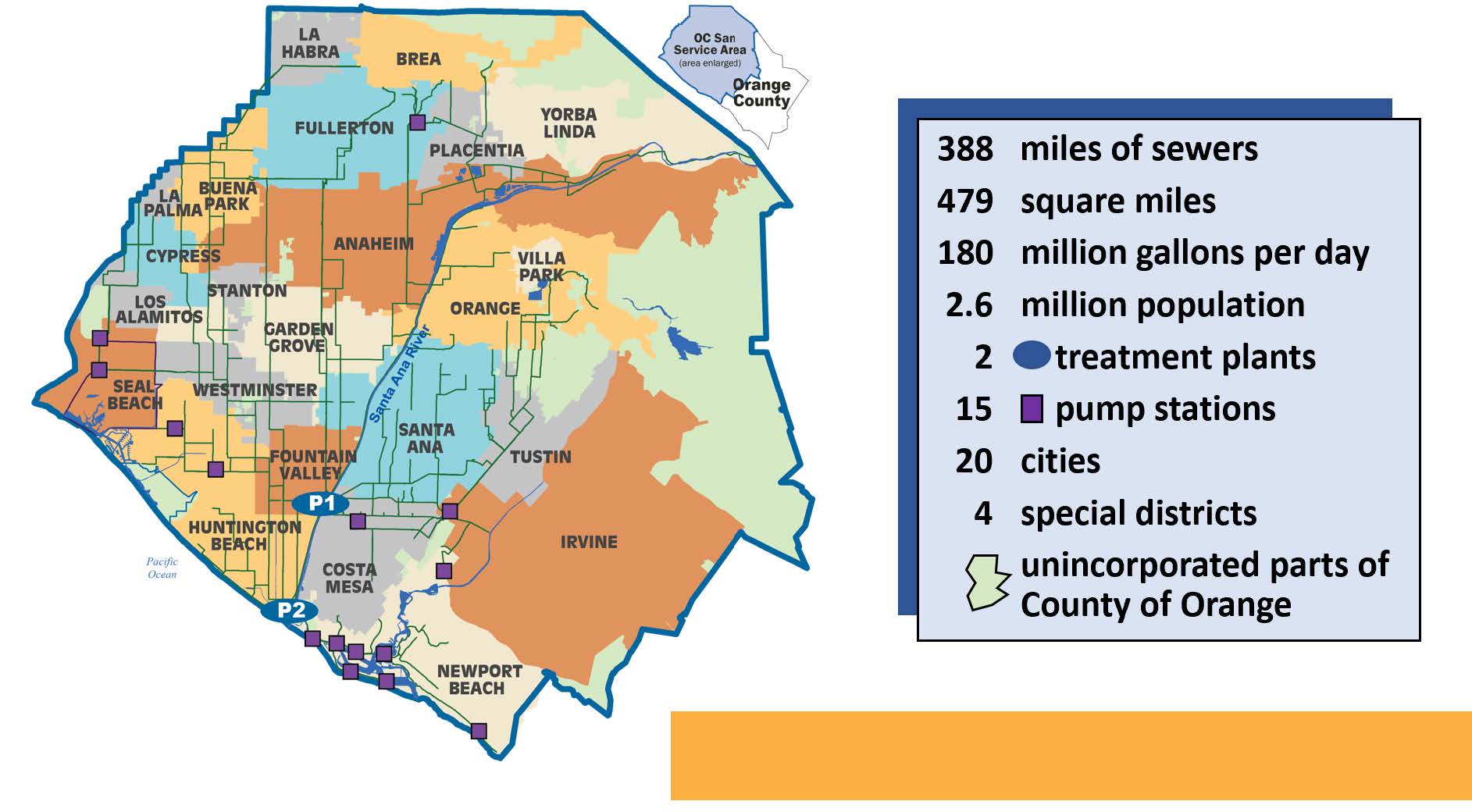 Project DescriptionBackgroundOrange County Sanitation District (OC San) operates a vast wastewater collection system that ultimately converges to a single point at the headworks facility at treatment Plant No. 2 in Huntington Beach, California (Figure 1). This unique location makes the headworks one of the most critical water pollution control facilities in the state. Continuous and reliable operation of the 317 million-gallon-per day (mgd) headworks is paramount to protecting the coastal environment, public health, and the regional economy. 
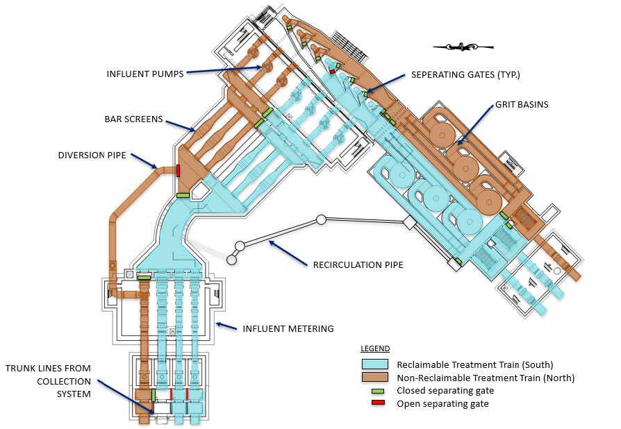
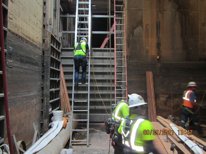
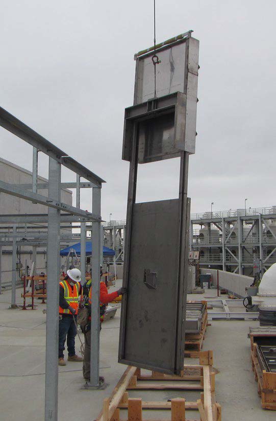
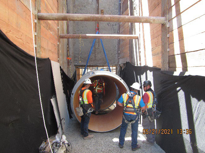
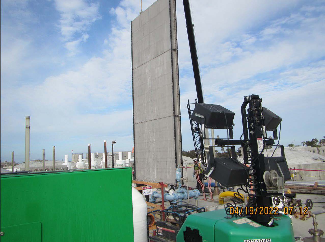
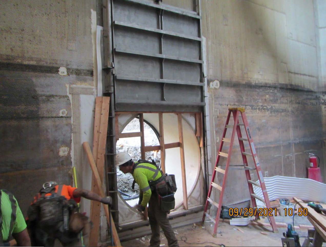
Nearly a decade ago the Orange County Water District (OCWD) began planning expansion of the nearby Groundwater Replenishment System (GWRS). To facilitate the expansion, OCWD needed more source water from OC San, which could only come from Plant No. 2. However, Plant No. 2 processes industrial flows that are considered “non-reclaimable” and would have to be managed through separate treatment than the GWRS bound flows. The problem was everything mixed in the single headworks facility, and building a new facility was cost and land prohibitive. The key to unlocking this critical resource was finding a way to physically split the facility into two separate treatment trains. But how could this be completed without jeopardizing the operation of this critical facility? The solution was the P2-122 project: a complex project delivered on time and below budget, even though construction began in February 2020 at the beginning of the COVID-19 pandemic. The success of the P2-122 project is a testament to the skill, dedication, and leadership of OC San, its employees, consultants, and contractors in unlocking a drought resistant water supply for generations to come. Integrated ApproachThe integrated approach started with the partnership between OC San and OCWD. Both agencies recognized the value of water through the entire life cycle and worked to maximize its benefit. This partnership resulted in OCWD funding the $30 million project through its successful efforts to obtain a low interest rate loan from the U.S. Environmental Protection Agency’s Water Infrastructure Finance & Innovation Act, while OC San led project administration. The decision to split the headworks was also a decision to embrace sustainability. Instead of abandoning relatively new assets and building an expensive new system, the existing system was modified, resulting in lower costs to ratepayers, reduced construction impacts, and reduced use of resources. ComplexitySpecific work elements demonstrating the complexity of the project include: Separating Gates and Diversion PipeThe project physically separated the headworks by installing 17 new large stainless steel slide gates in constrained areas (Figure 2). This work required extensive confined space entries to confirm the design dimensions for the new gates. 
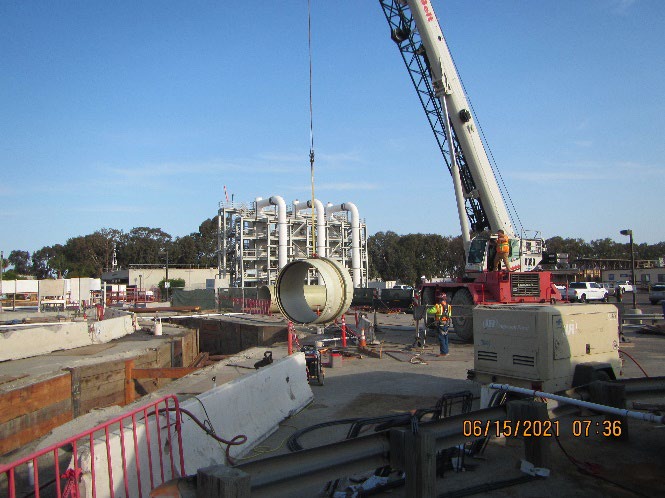
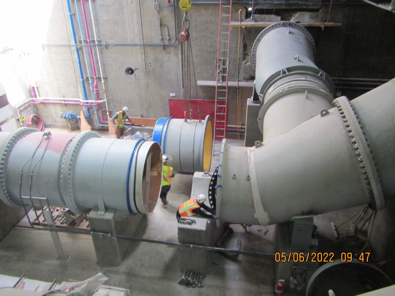
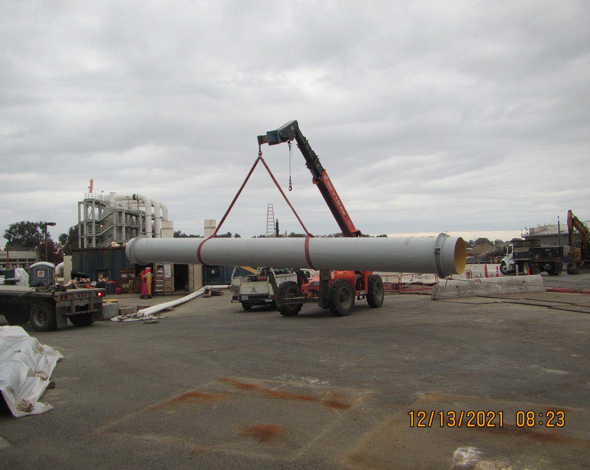
The project also included a new 75-inch diversion pipe, which had to be installed 30 feet below grade in a highly congested utility corridor adjacent to the critical facilities (Figure 3). This required a complex shoring system, custom steel fittings, and challenging wall penetrations through 36-inch thick concrete walls. 
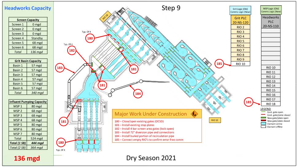
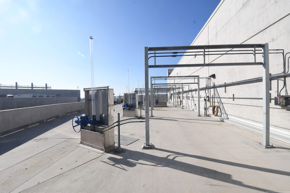
PLC SplitWith the headworks separated, the system controls had to be modified. The complexity of this task was amplified because the existing programmable logic controller (PLC) was already at capacity. Therefore, a new PLC had to be provided and the program split between the two systems. This change required running the entire headworks manually while the new system was installed. Construction SequencingThe project team developed a detailed sequencing plan with hundreds of steps, one of these steps is presented in Figure 4. The sequence had a major benefit of avoiding a full facility bypass, a high-risk, high-cost operation which was thought to be unavoidable during the planning phase. 
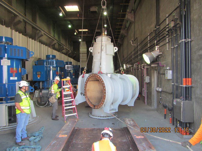
Originality and InnovationThe team deployed multiple innovative approaches to execute the project, including: Pumping Divergent FlowsWith the headworks split, the flows on each side are substantially lower, which would have caused problems with the existing pumps. This issue was resolved by replacing some of the existing large pumps with smaller pumps (Figure 5) custom engineered to provide a large flow range and fit in the existing space. 
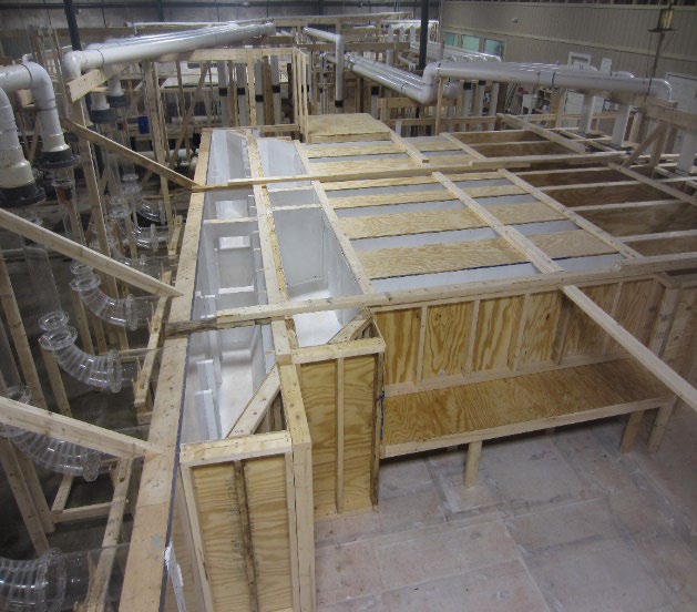
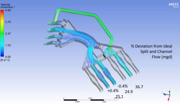
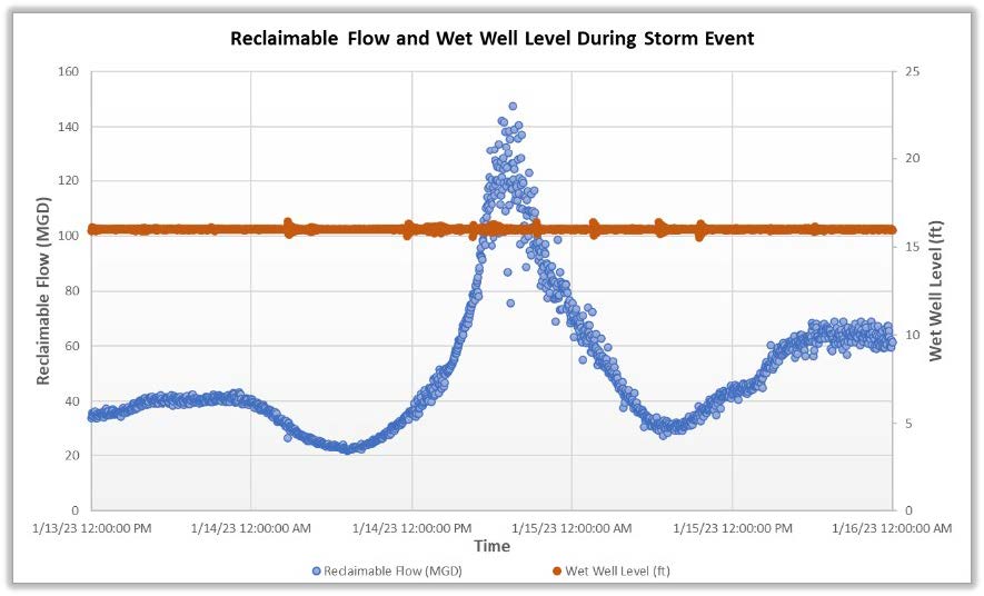
The tradeoff to providing the smaller pumps was a decreased wet-weather capacity. To offset this decrease, an innovative “over speeding” approach was used on the remaining pumps. By testing and reprogramming the large pumps to operate faster, their total capacity was increased by 50 mgd, offsetting the lost capacity from the smaller pumps without expensive replacement of motors and drives. Optimized Hydraulic ModelingThe modifications altered the system hydraulics and created a risk of adverse hydraulic conditions. Therefore, the project included a physical model of the influent pump station intake. This was supplemented by a computation fluid dynamics (CFD) model that covered the remainder of the facility. By combining CFD and physical modeling (Figure 6), the project team protected the system’s reliability. 
Quality
Contribution to Social or Economic AdvancementThe project contributes to social and economic advancement by providing sustainable source water to GWRS, which ultimately provides clean and safe drinking water to over one million people. This makes the system essential to the health and well-being of the community. This water source also requires less energy for transmission and treatment than many alternatives, resulting in a lower carbon footprint and improved air quality.  Click images to enlarge in separate window.
Click here to return to the list of 2023 winners. |
Our Partners