- Home
- Contact Us
- News & Events
- Awards
- AAEES Awards Criteria
- 40 Under 40 Recognition Program
- Edward J.Cleary Award
- Excellence in Environmental Engineering and Science Education
- Gordon Maskew Fair Award
- Honorary Member
- International Honorary Member
- Ralph and Joe Bales Graber Science Award
- Stanley E. Kappe Award
- Environmental Communications Awards Competition
- Excellence in Environmental Engineering and Science Competition
- The AAEES Chapter Blue Marble Award
- Resources
- AAEES Microcredentials
- Annual Reports
- AAEES Press Releases
- AAEES Website How To VIdeos
- Environmental Engineer and Scientist
- Environmental Engineering Body of Knowledge
- PFAS Resources
- Specialty Examination Guide
- Students and Young Professionals Resources
- Who's Who in Environmental Engineering & Science®
- Leadership Opportunities
- Membership
- Donate
- Jobs
2023 Excellence in Environmental Engineering and Science® Awards Competition Winner
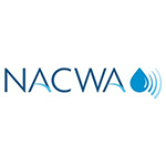
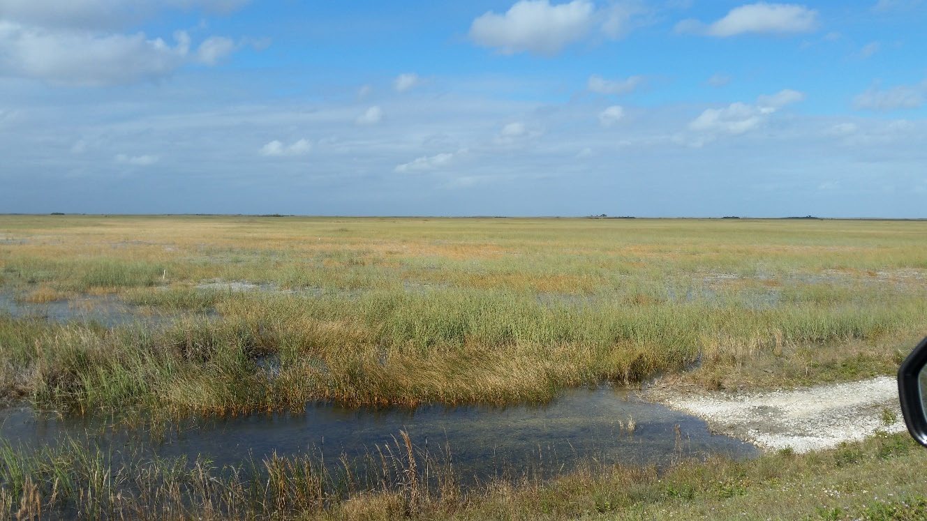
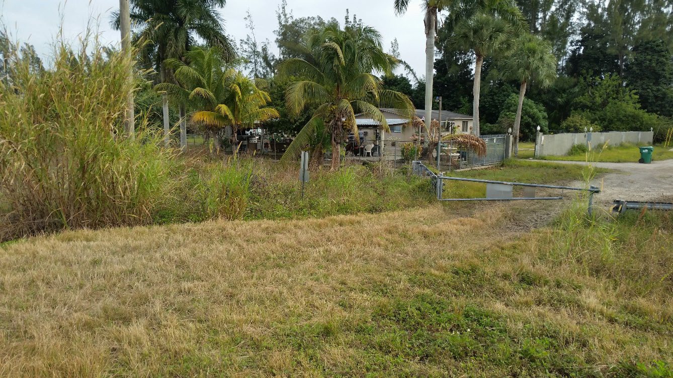
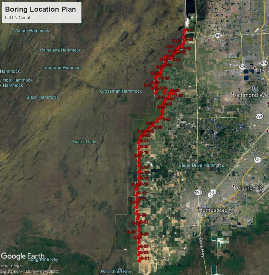
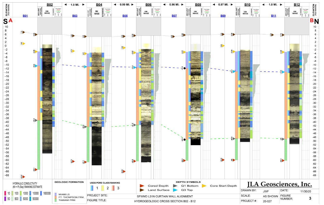
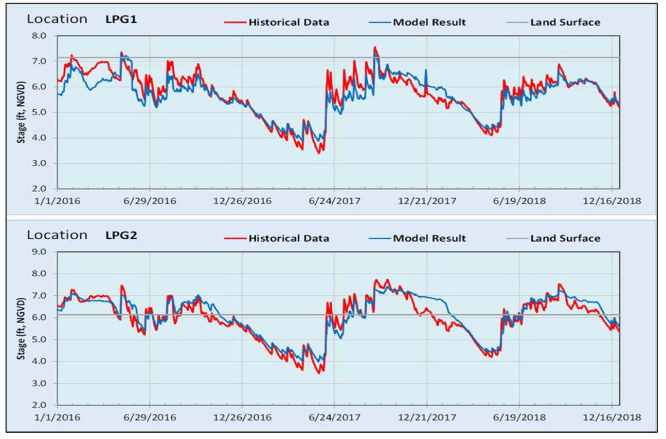
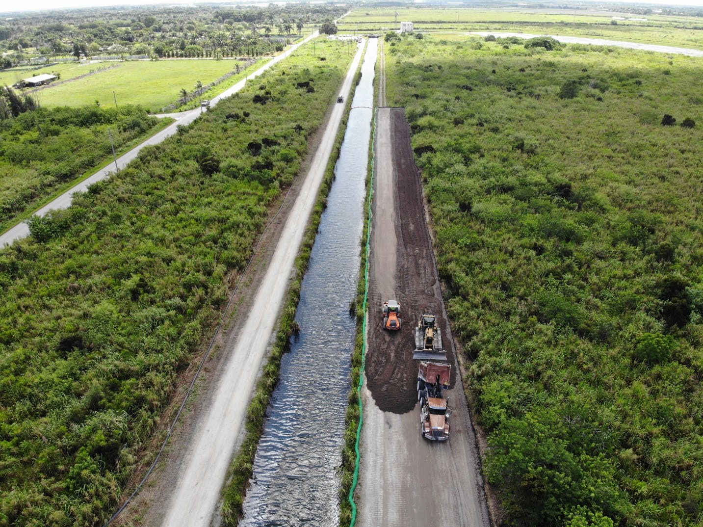
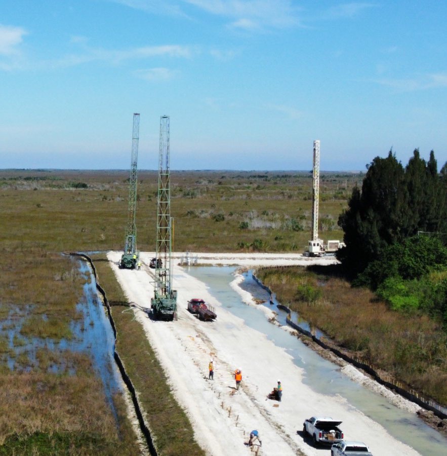
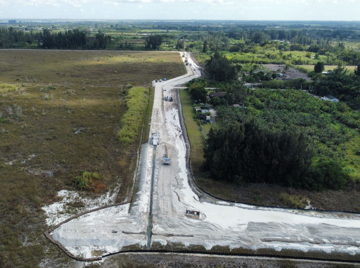
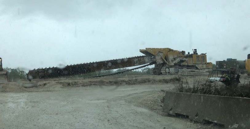
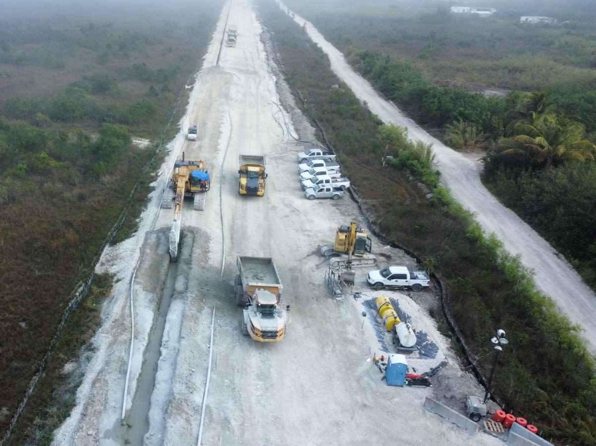
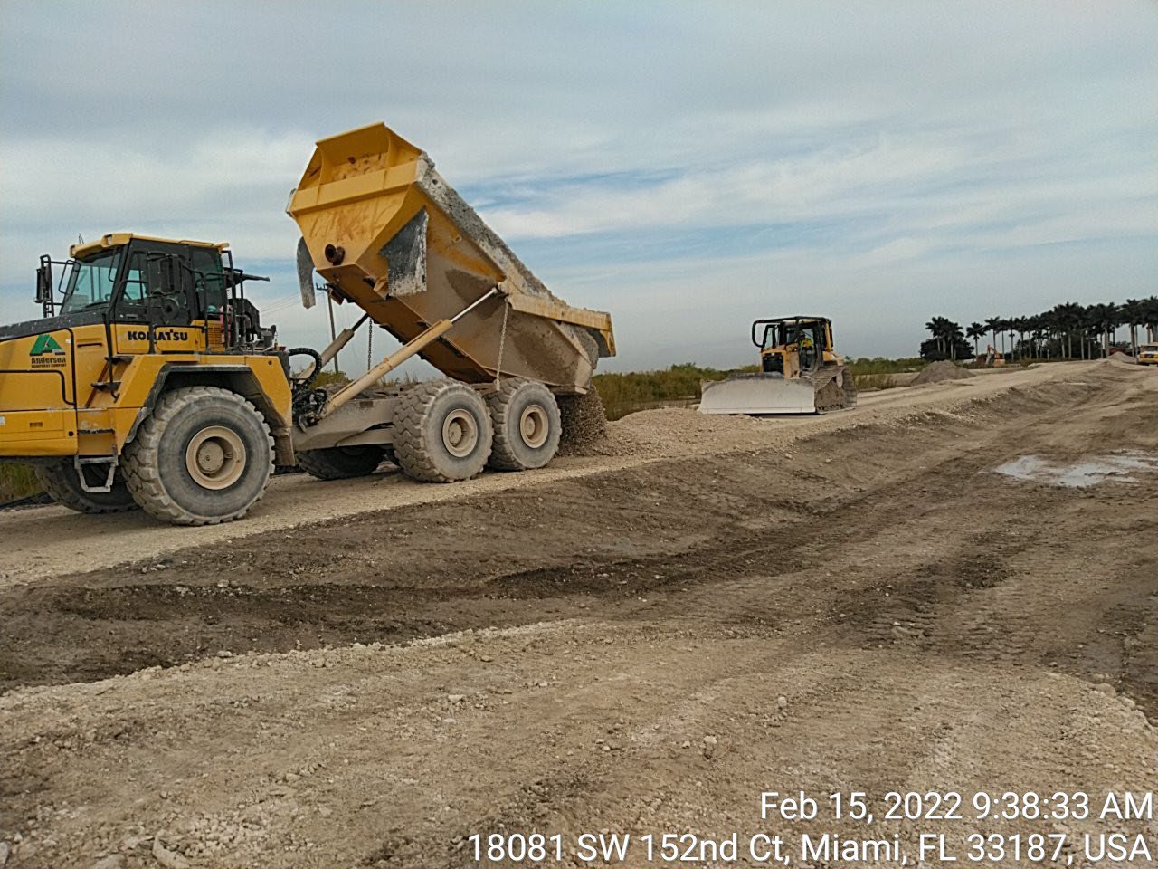
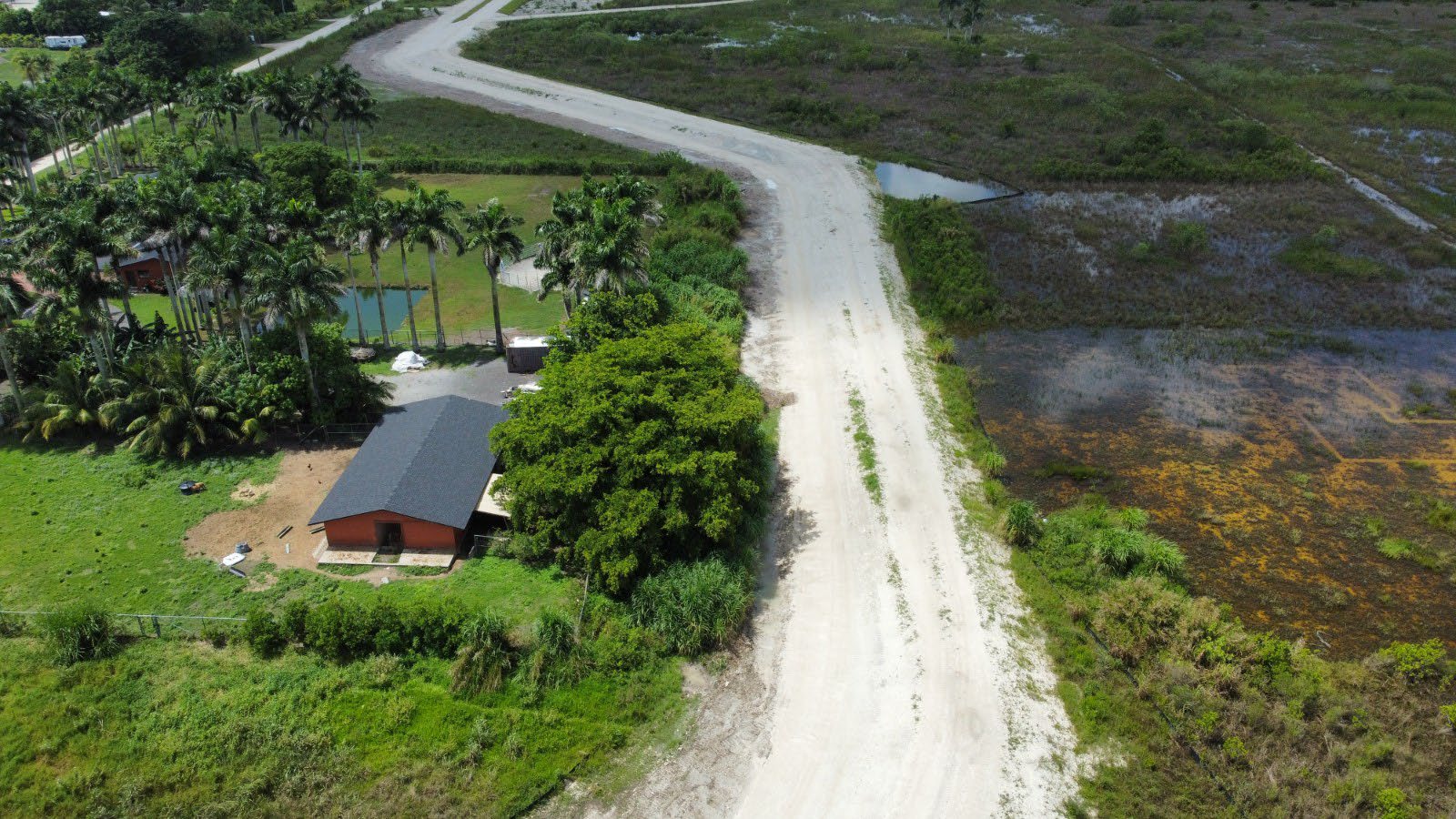
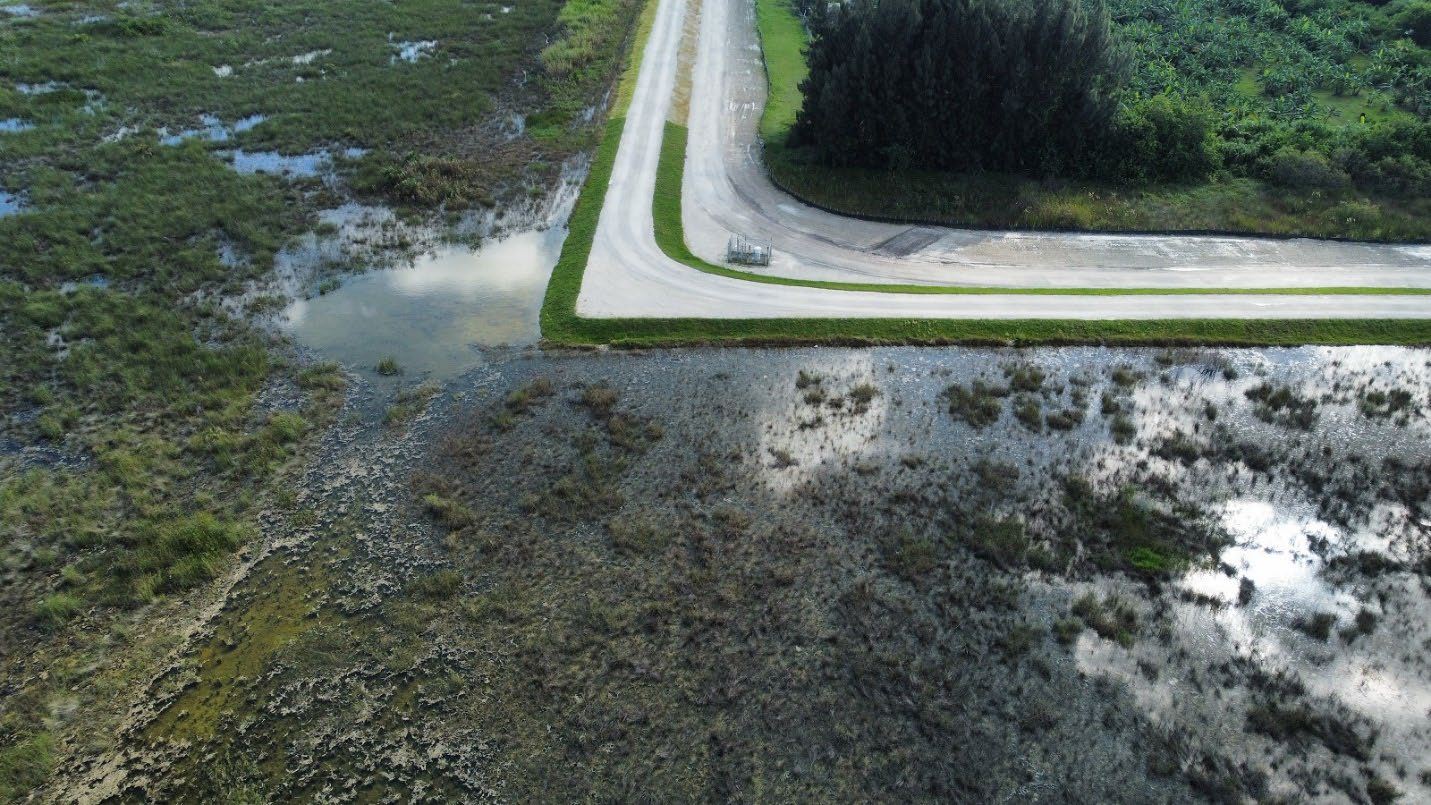
Honor Award - Environmental Sustainability8.5 Square Mile Area (SMA) Limited Curtain WallEntrant: The R.J. Behar & Company, Inc., Team Entrant Profile R.J. Behar & Company, Inc. (RJ Behar), as the prime firm, provided overall project management, civil and environmental engineering services. RJ Behar is a minority owned, small firm. RJ Behar completed the plans, specifications package, cost estimates, preliminary construction schedules and the Design Documentation Report (DDR). In partnership with the SFWMD and project stakeholders, RJ Behar managed the project from the overall geotechnical exploration, through design, bid assistance to construction completion and project certifications. The subconsultant firms of WSP geotechnical engineering; Tierra South Florida, Inc. geotechnical explorations; Widden Surveying & Mapping, Inc. land surveyors were instrumental in the project success. Golder Associates, Inc. geophysical logging; JLA Geosciences, Inc. aquifer parameters; and MacVicar Consulting, Inc. hydrogeological modeling were also involved in the project. The contractor for the project was Geo-Solutions, Inc. Project stakeholders included the U.S. Army Corps of Engineers (USACE), National Park Service, Miami-Dade County (MDC), Florida Department of Environmental Protection (FDEP), and United States Geological Survey (USGS). Project DescriptionDemonstration of a comprehensive, integrated approach that considers all environmental media, i.e., air, water, and land. For example, solution of an air pollution problem must not create a land disposal problem or an adverse water impact that is not addressed by the project.The 8.5 SMA Limited Curtain Wall (8.5 SMA) is part of the modification of the Central and Southern Florida (C&SF) Project for Modified Water Deliveries (MWD) into Everglades National Park (ENP) authorized by Section 104 of the Everglades National Park and Expansion Act of 1989 (Public Law 101‐229) as amended by the Consolidated Appropriations Resolution, 2003 (Public Law 108‐7), and SFWMD is the project sponsor. The 8.5 SMA is comprised of low‐density urban and agricultural landscapes. It is surrounded by levees and is adjacent to ENP on its western and northern borders and is adjacent to more intensively developed urban lands to its east. This area receives significant amounts of groundwater seepage from ENP, particularly during wet periods and there have been several projects and features constructed since 2000 to manage water levels within this location and surrounding areas as well as land acquisition. Flood mitigation required for 8.5 SMA is accomplished by managing groundwater levels primarily via operation of a series of canals constructed under the authority of the MWD project1. The MWD Project was authorized by the Everglades National Park Protection and Expansion Act of 1989 (P.L. 101-229) to improve water deliveries to ENP and, to the extent possible, restore the natural hydrological conditions within the park2. The modified water delivery to the ENP cannot be fully accomplished until an alternative is found that would mitigate the risk of flooding to the 8.5 SMA. Despite the previous efforts, the 8.5 SMA area still flooded for several months due to its proximity to the ENP, low topography, and lack of drainage. The intent of the project was to efficiently manage seepage to control groundwater flow and levee seepage, leaving the ENP and Water Conservation Area 3B (WCA-3B), while maintaining an appropriate amount of groundwater flow to minimize impacts to Miami-Dade County’s West Wellfield and appropriate levels of freshwater flows to Biscayne Bay. The project was subject of an environmental evaluation by the USACE, which studied several alternatives to the problem and was reviewed by Federal, State and local agencies, Tribes, input of the public, USACE staff, and was approved as a Finding of No Significant Impact (FONSI). The evaluation considered impacts to the environment including air, water, and land. The design approach included a comprehensive evaluation of geological formations, seepage flow modeling at project level as well as regional level, evaluation of impacts to existing wetlands, environmental sensitive species, evaluation of impacts to local roads, utilities, residential properties, evaluation of seepage management technologies, construction methods and others. The 8.5 SMA project was the first phase of seepage wall construction. The second phase is the Central Everglades Planning Project (CEPP) New Water Seepage Barrier, which broke ground in December of 2022. Quality as evidenced by the degree of user satisfaction and proven performance. (For RESEARCH projects, testimony of experts in the field as to the quality and importance of the research will be used in lieu of user satisfaction or proven performance. For REGULATORY PROGRAMS, quality will be decided based on demonstrable impacts of the effort.)“Today’s groundbreaking of the Central Everglades Planning Project (CEPP) New Water Seepage Barrier Wall marks another meaningful step forward in our journey to restore America’s Everglades," said Cara Capp, Senior Everglades Program Manager, National Parks Conservation Association. "This underground infrastructure will keep more clean water in the Everglades – particularly in the dry season when it is desperately needed. Park advocates look forward to the day when the benefits of multi-billion dollar investments in ecosystem restoration can be fully realized and clean water flows south to Everglades National Park and Florida Bay.” In a collaboration between the South Florida Water Management District and the Army Corps of Engineers, 4.9 miles of new seepage wall — the Central Everglades Planning Project New Water Seepage Barrier — will be built as a northern extension to the 2.3-mile curtain wall adjacent to the 8.5 SMA that broke ground last year. Rainfall events have proven that the first section of the wall effectively reduces flooding, but the extension will be necessary to ensure flood protection from restoration efforts that will eventually bring even more water to an Everglades that desperately needs it.3 Originality and innovation, representing the application of new knowledge, a new application of existing knowledge, or an innovative mix of existing knowledge.Cutoff walls are not a new technology. According to the USACE Manual 111-2-1913, Design and Construction of Levees, a cutoff beneath a levee to block seepage through pervious foundation strata is the most positive means of eliminating seepage problems. The manual also indicates that cutoff walls are not economically effective to depths of more than 40 feet. The 8.5 SMA project required a cutoff wall at depths of 55 to 65 feet. The cutoff wall would be constructed down through the flow zones in the Biscayne Aquifer and terminate and key into denser, low permeability zones of the underlying Tamiami formation (considered a semi-confining unit). Major considerations in the design of a cutoff wall included composition of the wall (with or without cement), shear strength, and flexibility. The cutoff wall is constructed by filling the trench with a mixture of native soil and bentonite [Soil Bentonite (SB) wall], or cement and bentonite [Cement Bentonite (CB) wall], or soil, cement, and bentonite [(SCB) wall)]. For this application, with very little on-site soil available due to the limestone being close to ground surface, the CB wall was considered the best alternative. In addition, the rock has large voids and solution cavities, especially in the high flow zones, and the cement in the backfill mix will penetrate these voids and plug them as the cement sets up, whereas a SB wall might not be able to plug the voids and could lead to a collapse of the slurry trench4. In order to achieve the design intent, the Contractor for the project utilized an assembly line type approach in which they blasted through the lower layers of the limestone formation, then behind, used a chainsaw trencher to cut through the upper limestone layers (above 40 feet), temporary filled the trench with cuttings and spoil, then re-excavated the trench using a long-reach excavator and finally filled the trench with the cement bentonite (CB) mix. The CB mix was mixed on site using a temporary batch plant. The complexity of the problem addressed.Cutoff wall design presents challenges in terms of optimizing cost, constructability, and performance. Obviously, performance cannot be compromised. A cutoff wall can fail to perform as a cutoff for several reasons, most commonly caused by trench instability, incorporating zones of higher hydraulic conductivity/permeability soils within the wall (so-called windows) or failure to terminate the wall in a low permeability stratum. All of the potential causes of performance failure must be considered and prevented4. The limestone formations in the project area were found to be extremely porous and at the same time, variable in strengths. Estimated transmissivity values ranged from approximately 105,300 to 1,047,100 ft2/day. The selection of the cutoff wall depth was done by developing a local hydrogeologic model and evaluating the seepage flows at various depths of seepage wall. The time period of the simulation included a three year very wet period. The SFWMD evaluated the possible impacts to the region with a regional model to meet the goal of maintaining an appropriate amount of groundwater flow and minimize impacts to Miami-Dade County’s West Wellfield and appropriate levels of freshwater flows to Biscayne Bay. The project had to gain approval from the USACE under the Section 408 review process, while meeting the project goals, keeping the costs reasonable, and receiving the approval by environmental agencies such as the FDEP. To ensure that the type of wall selected was the most cost-efficient design, the project was advertised allowing either SB wall, CB wall, or SCB wall to be provided. This required developing specifications for the three systems. In order to validate the construction methods used, including the blasting design, a 500-feet test levee section was constructed over the alignment to verify that the existing levee would not experience excessive deformations that would change crest height/slopes and for data collection to establish allowable performance thresholds. The final construction included the construction of a 2.3-mile seepage cutoff wall made of a mix of cement and bentonite slurry along the L-357W levee northwest of the S-357 pump station, and along the south side of the C-358 canal. The seepage cutoff wall was constructed through the approximate center of the L-357W levee. The approximate depth of the curtain wall was between 55 to 65 feet deep below ground, with an approximate thickness of 28 inches. The extent to which the project contributes to or offers the prospect of contributing to social or economic advancement.The Environmental Assessment performed for the project concluded that the 8.5 SMA (Las Palmas) Community would benefit from the construction of the proposed action and that the proposed action would not result in disproportionately high and adverse human health or environmental effects on minority populations and low‐income populations. The area has already seen reduced flooding during recent rain events with more water remaining in the ENP and flooding of the nearby Community reduced. This will directly benefit the quality of life to the residents. ENP preserves the largest subtropical wilderness in the nation, a vast natural area in the southern Everglades and Florida Bay known throughout the world for its unparalleled ecological values, natural hydrologic conditions, vibrant cultural heritage, and unique recreational and educational opportunities. As the first national park designated for the protection of biological resources, ENP is the only place in the United States jointly designated as an International Biosphere Reserve, a World Heritage Site, and a Wetland of International Importance5. A major goal of Everglades restoration is to deliver more water to the ENP. This new underground seepage wall allows SFWMD water managers to support Everglades Restoration goals by sending even more water into ENP. The project affords increased system-wide flexibility under the approved water control plans. The project will enable restoration of more natural hydrologic conditions using three dimensions: timing, location, and volume of water. Footnotes
Click images to enlarge in separate window.
Click here to return to the list of 2023 winners. |
Our Partners